Dross Formation & Control
Published:
This technical module defines the several different components of galvanising line dross, and the specific mechanisms which generate each of them. Based on that understanding, the process conditions related to dross formation are identified, and control strategies for minimising dross are outlined. It forms part of a series of galvanising line technical reference modules authored by Steven W Hesling.
1. Introduction
Dross consists of inter-metallic particles, oxide films and a high proportion of entrained zinc. The dictionary definition of dross is “oxides and other refuse which accumulate on and within the surface of a molten metal bath, requiring removal by skimming”. That describes most, but not all, galvanising line dross. One specific type of dross particle sinks to the bottom of the zinc bath, and operators call this Bottom Dross, while the more usual floating particles create Top Dross. The term Skimmings is also encountered: it refers to dross taken from the bath surface near the air knives, which contains a substantial proportion of oxide film.
Dross particle formation is associated with variation in the temperature and composition of the bath metal. Oxide films are created mostly at the coating mass control knives, through interaction with high velocity air. Entrained zinc can account for as much as 90% of dross by mass. Good drainage and a small number of other actions help, and new technologies are being pursued, but for the moment there is still no established way to substantially reduce this loss.
Dross is a persistent issue in hot-dip zinc galvanising lines:
- Removal of dross from the bath surface involves regular heavy manual work in unpleasantly hot and noisy conditions. Some lines now have expensive robots doing this, both to relieve operators and to improve consistency.
- Dross increases coating metal consumption by 5 to 10%, incurring substantial cost.
- Dross particles are a source of defects. They are an especially serious issue for critical automotive exposed and other high-value coated products.
This module aims to provide useful dross-related information for all operators of zinc galvanising lines. Its focus, however, is high value product manufacturing, where the greatest issues and the greatest opportunities exist.
Zinc galvanising lines make two different coating types, with fundamentally different dross generation characteristics. Both are addressed here. Conventional Galvanised has a bright, soft metallic zinc coating, and is conveniently referred to in the literature as GI.
Galvanneal has a hard, dull grey coating consisting of iron/zinc alloys, developed in a furnace located after the coating bath and air knives. It is very often abbreviated to GA. The name is unfortunate, because the heating process the coating undergoes is not annealing in the conventional metallurgical sense. A much better name is “alloy coat”, which never really became established but may occasionally be encountered.
2. Process Overview
A galvanising line zinc bath normally contains between 150 and 300 tonnes of liquid metal, consisting mostly of zinc. Metal mass is partly a function of product width, but larger baths have significant advantages and are becoming more common. Stable temperature and composition are essential for reducing dross, and both conditions are made easier by a greater mass of coating metal.
The bath is contained in a refractory-lined, induction-heated steel vessel commonly referred to as the pot. Associated equipment includes the furnace snout, which extends below the surface of the bath, a sink roll and one or two stabiliser rolls.
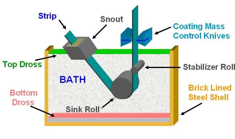
The snout delivers hot, clean strip from the protective atmosphere furnace into the bath without exposing it to air. Strip in this condition reacts quickly with the bath metal, providing a strongly adherent bond. Submerged rolls then direct and stabilise the strip as it moves upwards to the coating mass control air knives, located about 0.4 metres above the bath.
The air knives are very much part of bath processes, and are a major source of dross. Zinc close to the strip surface moves upwards from the bath towards the knives, where interaction with high velocity air generates oxide films, and where cooling creates dross particles. A downwards counter-current flow then transports dross and excess zinc back into the bath.
Zinc bath temperature should be close to 465°C and must be kept as stable as possible. Strip entry temperature is normally held between 0.0 and 5.0°C above bath temperature. Correct incoming strip temperature reduces the firing rate of the induction heaters and the stirring action these generate, which matters because automotive producers seek to minimise bath agitation. Correct temperatures also promote good chemical reaction between the strip surface and the bath metal.
Zinc ingots weighing 1 to 3 tonnes are added to replace coating metal and dross losses. Normally they are placed in the bath between the snout and the back wall of the pot. The lowering rate of cold ingots is controlled to maintain a steady bath level, and to minimise bath temperature disturbance.
Some lines have small pre-melt pots which supply molten metal into the main galvanising line bath. This has some advantages, but pre-melt units are difficult to justify in zinc galvanising lines. They are much more important in Galvalume and aluminising lines.
When making conventional bright metallic GI product, aluminium is added to the bath to maintain a concentration of 0.20 to 0.26%. There it reacts with the strip surface, creating a layer which is essential for good coating adhesion. This bath composition forms floating top dross particles. Because both the strip surface reaction and dross particle formation consume aluminium, an addition rate of 0.50 to 0.70% is normally required to hold bath concentration in the desired range.
The distinctly different product made in zinc galvanising lines is Galvanneal, which has a dull grey iron/zinc alloy coating developed in a post-coating induction furnace. It is valued for its paint adhesion and spot-welding characteristics, and is used by vehicle and appliance manufacturers. In this case bath aluminium is maintained at or slightly below 0.135%, and this composition forms slowly sinking bottom dross particles.
A chemical reaction layer still forms on the strip surface during Galvanneal production, but it is only temporary and breaks down in the post-coating galvannealing furnace. Layer stability is important. Coating mass is strongly affected by substrate roughness, and premature layer breakdown can result in rough “outburst” structures which make coating mass very difficult to control.
3. What Dross Consists Of
Three distinct solid materials contribute to the mass of dross formed in a galvanising line bath.
Oxide Films
Oxide films are created primarily at the air knives, where high-velocity wiping gas interacts with the liquid coating metal. Higher line speeds and lighter aim coating weights both require increased knife pressure and reduced knife-to-strip distance, and both effects increase the rate of oxide film generation. A much smaller amount of oxide may also come from the skin of metal ingots added to the bath. Oxide film contributes to Top Dross: it floats on the bath surface and is carried by bath metal flow away from the strip, accumulating against the snout and other nearby equipment.
Fe2Al5 Particles
These particles are significantly less dense than the bath metal and quickly rise to the surface, contributing further to Top Dross. They form when bath aluminium exceeds 0.140%, during the manufacture of GI coating, and precipitate from the bath wherever metal temperature is reduced – or wherever aluminium concentration increases. Because the bath is permanently saturated with iron dissolved from the strip surface, these conditions force iron out of solution as top dross particles. Such cooling occurs characteristically at the air knives, and in the region behind the snout where cold coating metal ingots are added to the bath.
FeZn7 Particles
Slightly denser than the bath metal, these particles sink slowly to the pot floor, producing Bottom Dross. They form during GA production, where bath aluminium is below 0.135%. The mechanism which creates them involves the same temperature and bath composition change that produces top dross. However, with less aluminium present in the bath, it is iron-zinc rather than iron-aluminium compounds that precipitate. Bottom dross is troublesome: it is difficult to remove from the bath floor, and its comparatively large particle size causes significant defects if it becomes entrained in the coating.
| Material | Typical Particle Size | Density | Dross Type |
|---|---|---|---|
| Fe2Al5Znx | 10–15 microns | 4.7 g/cm³ | Top Dross |
| FeZn7 | 80 microns (occasionally larger) | 7.1 g/cm³ | Bottom Dross |
| Liquid Zinc | — | 6.7 g/cm³ | — |
4. Formation Mechanisms: Temperature and Aluminium Instability
It is worth beginning with a very simple practical explanation of the physical principles involved.
Liquids often dissolve solids. Sugar added to hot coffee dissolves quickly, and more sugar can be dissolved in hot coffee than in cold water. Stated technically, the solubility of sugar in water increases with temperature. When water has dissolved all the sugar it can, it is said to be saturated. The same applies to salt, whose solubility also changes with temperature, although less markedly than for sugar.
Things become more complicated if we want to dissolve both salt and sugar in the same glass of water. The more sugar there is in the water, the less salt it is able to dissolve. And the more salt there is in the water, the less sugar it is able to dissolve.
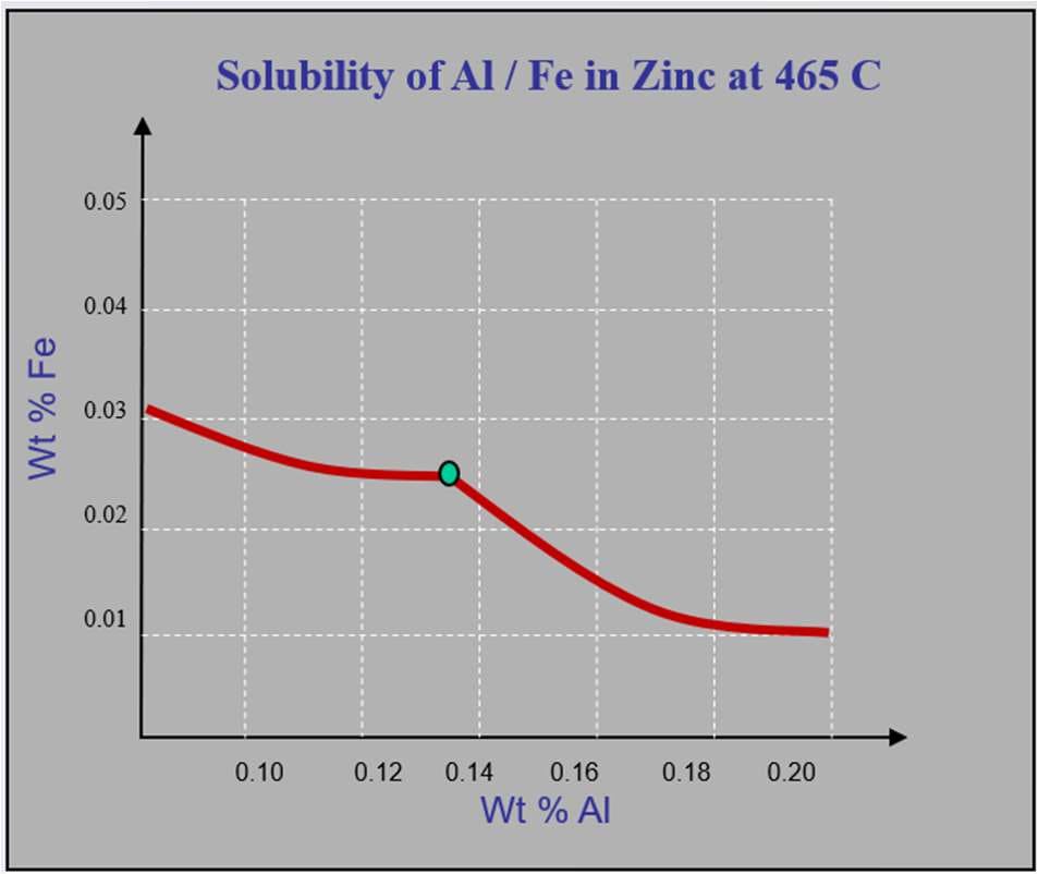
Now replace the glass of water with a galvanising bath full of zinc, and replace the salt and sugar with iron and aluminium. There is always plenty of iron available to dissolve from the strip, rather as if a large pile of sugar were sitting at the bottom of the glass. The availability of iron cannot be changed, but the amount of aluminium added is under our control.
The solubility curve indicates that a zinc bath can dissolve 0.135% Al and 0.025% Fe at the same time, as shown by the small green circle. If sufficient aluminium is then added to bring bath concentration up to 0.20%, the previous iron concentration is no longer possible – it must decrease to about 0.01%. The only way this decrease in iron concentration can occur is by rejecting iron from the liquid and forming solid iron-rich inter-metallic particles: in this case top dross particles consisting of Fe2Al5.
Whenever bath aluminium is below 0.135% the situation is a little different. Dross particles still form, but there is not sufficient aluminium available to make Fe2Al5. Instead the particles are FeZn7, which form bottom dross.
In summary, to avoid dross particle formation it is essential to maintain a constant aluminium percentage:
- Increasing aluminium means that percentage iron must decrease. It is rejected from the bath in the form of iron-rich dross particles.
- Decreasing aluminium will not immediately form dross, but it will allow more iron to dissolve. Then, when aluminium is eventually returned to its initial level, all the recently dissolved iron will be rejected – again in the form of dross particles.
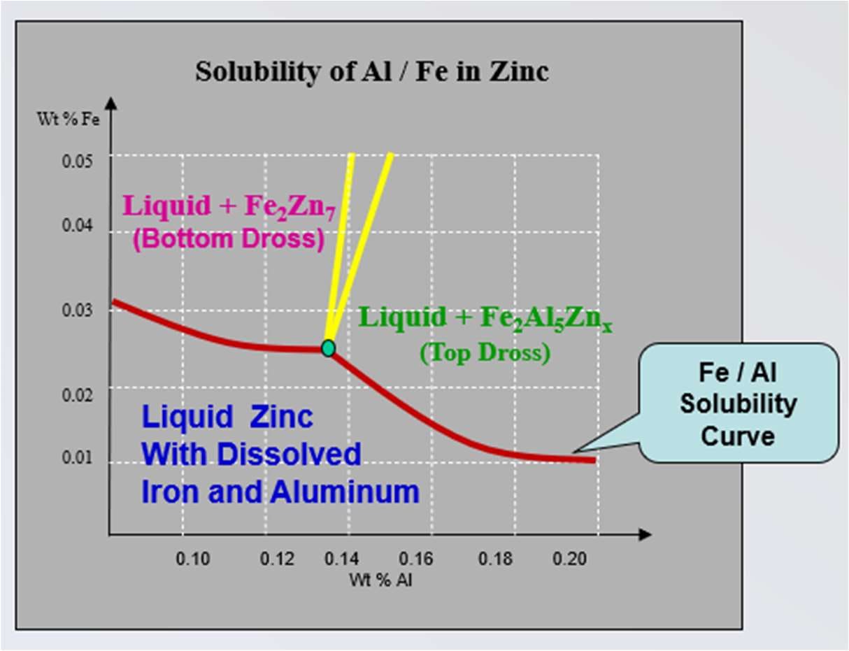
The graph above summarises bath constituents for various analysis ranges. Data from it can be used to make bath analysis change calculations – for example, to estimate how much dross generation will result from any particular increase in percentage aluminium.
It is sometimes required for both Galvanneal and Galvanised coatings to be made on a single line, with a single pot. This requires transitioning to and from bath chemistries of about 0.135% and 0.25% aluminium rapidly, with minimum downgrade product and, of course, minimum dross generation. The situation became critical during the 1990s as automotive demand for both products increased dramatically. It led to a large increase in knowledge about the galvanising process, and to the development of new technologies such as Yamari sensors for continuous real time monitoring of bath aluminium.
The solubility boundary for iron and aluminium in zinc also changes with temperature, forming the family of curves shown below. This creates a situation similar to that which occurs through changes in bath chemistry:
- Decreasing bath temperature decreases solubility, causing dross to form.
- Increasing bath temperature dissolves more iron, which will create dross whenever temperature is returned to its previous value.
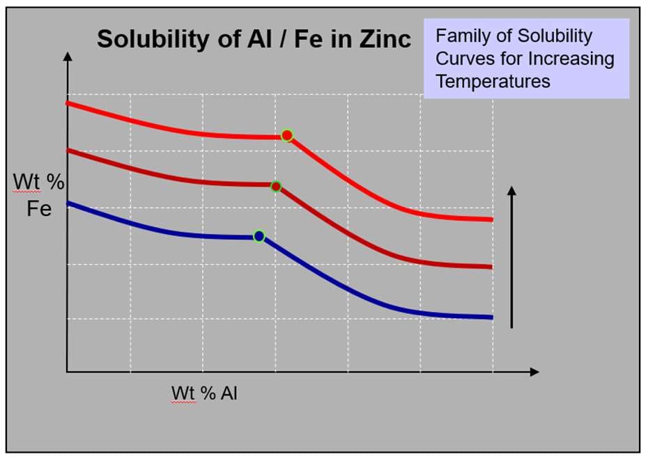
Dross formation does not require a change in the temperature of the entire bath. It is enough for cooling to occur in specific locations. This happens continuously at the air knives, where bath metal is cooled by the wiping gas stream, and wherever cold make-up ingots are added at the back of the bath.
5. Control of Bath Temperature and Aluminium Concentration
The importance of maintaining stable temperature and composition in the bath was set out in the previous section. Achieving these objectives, however, has its challenges.
Bath Temperature
Bath temperature stability is the easier of the two, because it fits within a conventional control scheme. Temperature is continuously measured by thermocouples and can be automatically corrected by adjusting inductor power as required.
The secondary issues are not major. Strip entry temperature variation will be minimal if the furnace is operating correctly, and the temperature errors which do occur should be brief and mostly associated with product transitions. Rapidly lowering a cold zinc ingot into the bath decreases bath temperature by several degrees, depending on bath size and ingot mass. It is not difficult, though, to provide a slow lowering mechanism which extends immersion time to close to the normal interval between ingots, and thereby greatly improves bath temperature stability.
Automotive lines utilise even more sophisticated systems, with lasers for precise bath level measurement. These have an additional purpose. Automotive manufacturers may slowly lower bath level when making critical exposed product, to avoid releasing zinc dust and other debris which accumulate on the inner walls of the snout and create defects if they attach to the strip. Bath level is then increased again while making non-critical product.
Measuring Bath Aluminium
Controlling aluminium in the bath is a much more complicated challenge, and the first issue is measurement. Continuous aluminium sensors are expensive, have a limited life, and the early versions were prone to drift rather than failing outright.
Chemical analysis samples work, but have issues also. They need to be taken from well below the bath surface, and chill cast in suitable moulds to minimise segregation. Contamination with dross particles is a further issue, although there are calculations available for correcting this. And the time taken to get results back from the laboratory is too long for effective real time control. In practice, the main uses for chemical analysis results are to give operators confidence that things are progressing more or less as they should, and to support the development and tuning of aluminium consumption models.
Adding Aluminium
The next question is exactly how aluminium is added, and how that addition is controlled. Full size jumbo zinc ingots of one tonne or more are ordered and received with whatever aluminium percentage is requested.
Aluminium consumption varies significantly by product. With normal Galvanised, about 200 milligrams of aluminium per square metre are consumed by reaction with the strip surface. In addition, the coating itself has an aluminium composition similar to that of the bath, and dross particles remove a further significant quantity.
Dubois has indicated that this aluminium loss to dross formation is a function of coating mass, and this is supported by the author's own work. Dross generation is not actually affected by coating mass, but rather by the air knife pressure and distance used to achieve it. Maintaining bath aluminium at 0.25%, in a line making a wide product range including light coatings, will probably require an addition rate averaging about 0.6% aluminium.
Historically, lines may have had one composition of full size ingots, and then trimmed bath composition as required by manually adding 10 kg bars of pure zinc or of 10% aluminium/zinc alloy. This never worked well, in part because of inconsistent aluminium yield: the 10% bars tended to float and mix in with surface dross rather than with the bath. The transition to 5% aluminium bars was a step forward, since these sink to the bottom of the bath and give a more consistent and predictable aluminium yield.
Ultimately, the method adopted for aluminium addition control in modern lines involves a ratio addition procedure. The line orders full size coating metal ingots in two different aluminium compositions. One has slightly less aluminium than is ever needed, and the other slightly more aluminium than is ever needed. These two compositions can then be added in various ratios, delivering any percentage of aluminium required for a specific product.
Predicting Aluminium Consumption
That leaves one more major issue to consider. Responding to the chemical analysis of bath samples taken one or two hours ago is not an effective strategy, especially if the product mix has changed and the line is now making something different. It is much better to develop an aluminium consumption model, and to supply aluminium into the bath based on predicted consumption for the products scheduled to be manufactured during the coming 8 or 12 hours.
This is not as complicated or difficult as it may sound. It requires a few months of production history, together with aluminium and zinc addition records and bath analysis results, held in a spreadsheet. The Dubois aluminium consumption formula is then applied, and its coefficients adjusted as required so that predicted and actual numbers correspond.
This approach has an additional benefit. If predicted and actual numbers ever cease to correspond, that is a clear indication of something fundamental having changed in the coating process, and it needs to be investigated immediately.
6. Air Knives: Coating Mass Control and Dross Generation
Air knives are a complicated technology, but the basic ideas do not require an education in fluid dynamics to understand reasonably well.
Strip exiting a galvanising bath vertically carries coating metal with it. The actual quantity is a function of line speed, the density and viscosity of the liquid metal, and the roughness of the strip. In almost all cases this quantity of metal is far in excess of the required coating mass.
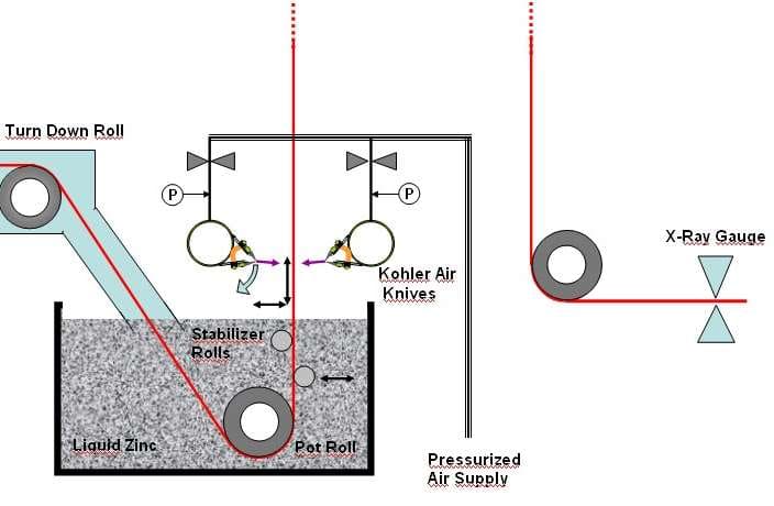
Air knives consist of plenum chambers – in this case simply large tubes – from which air flows through baffles and finally through a slot between two parallel knife lips. Wiping gas reaches high velocity as it passes through the knife slots, and at high knife pressures these flows can approach sonic velocity. Air knives are loud.
Both knife-to-strip distance and wiping gas pressure are adjusted to control coating mass. Such adjustment may be made to meet a changed coating target, or it may be necessary in order to continue meeting the same target after changing an operating parameter such as line speed. Almost all lines have an X-ray coating measurement gauge feeding back to an automated closed loop coating mass control system.
The effect of a knife stream impinging on the strip is to create both a pressure distribution and a shearing action as the gas deviates away from its initial path.
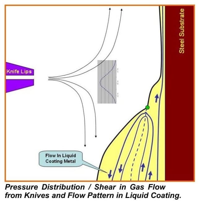
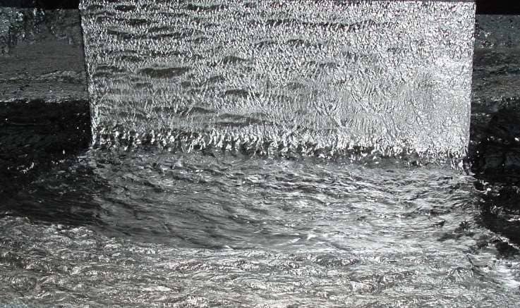
The figure alongside shows both the gas stagnation pressure distribution from an impinging knife flow, and the gas flows diverging away across the surface. These conditions reduce coating mass by two mechanisms. The pressure field resists transit of the zinc, while the downwards flow of air pulls coating metal back towards the bath through a process of viscous drag. This interaction between downwards air flow and bath metal continues all the way to the bath surface, and creates a characteristic appearance on the strip.
Liquid flows within the coating metal are also shown. The dotted line is a neutral plane in which there is no net flow of zinc, and the green dot indicates the position where surface flow reverses and begins moving upwards rather than downwards with the strip.
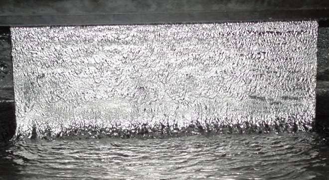
The most severely dross generating condition occurs when unstable air flows, high pressures and, frequently, upwards knife angles combine to completely destabilise the surface of the liquid on the strip. The result is a coating separation condition called “splashing”.
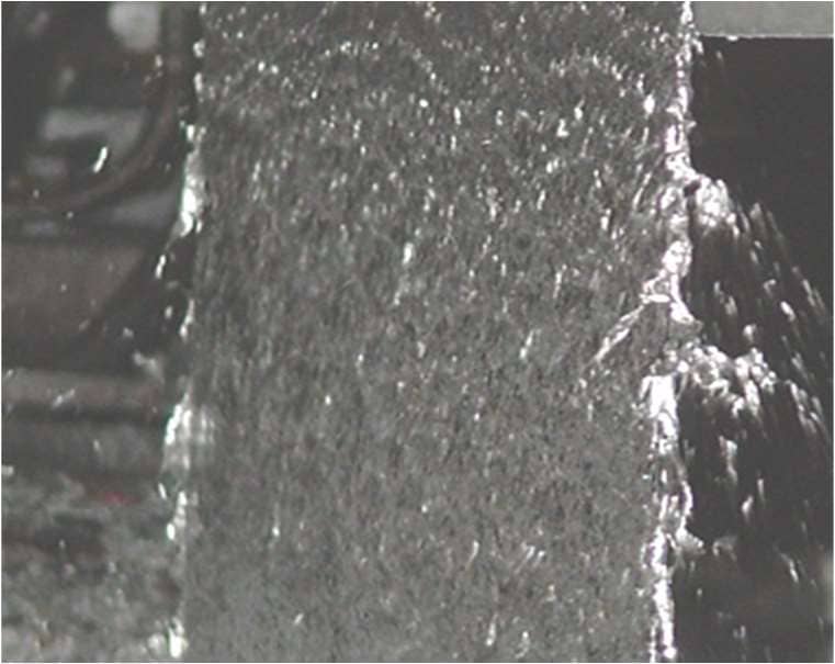
Optimal conditions for minimum dross generation involve a small knife gap and minimum knife-to-strip distance. These are employed in automotive exposed lines making very high quality product with leading edge control. More basic lines may not be able to maintain similar operating conditions. Greater knife-to-strip distance might be mandated, for example, if there were concern about poorly controlled strip waves or buckles causing knife-to-strip contact.
It should also be noted that air knives are line speed limiting in most coating lines, restricting line speed to about 170 or 180 metres per minute. Continuous annealing lines – which are basically galvanising lines without the zinc – can easily exceed 200 metres per minute. Operators looking for output may therefore push into speed ranges which are not optimal for other parameters. Air knife design, setup and coating mass measurement are covered in detail in the companion module on air knife technology and coating mass control.
7. Economic Impact of Dross
Dross formation and removal directly increases zinc consumption and therefore manufacturing cost, in addition to the separate cost of coating defects.
Coating Metal Loss
Dross is typically removed at rates of 8–16 g/m² of product, though various process problems can push this figure above 20 g/m².
Expressed differently, a net loss of US$1.15m from 12 g/m² of dross implies close to US$100,000 a year for each gram per square metre. It is arguably more useful to state it that way round: an average line can save in the order of US$100,000 per year for every 1 g/m² reduction in dross generation.
Product Defects
Dross particles are also a direct source of coating defects, causing occasional rejection of high-value automotive exposed products. There is little or no downgrade market for this material, given the mechanical property and coating weight requirements specific to automotive applications. To limit this exposure, automotive lines typically invest in state-of-the-art inspection equipment and deliberately schedule non-critical coils into production sequences to allow for dross skimming and ingot additions without risking exposed-quality material. The cost of this lost production capacity is difficult to quantify precisely, but is understood to be substantial. Dross-related defects are far less of an issue for lines producing commercial and commodity-grade product.
8. Dross Removal and Drainage Practice: GA / GI Transition
Top Dross Removal and Drainage
Physically, top dross can be removed from the GI bath surface at any time. Removal may be avoided, however, during production of ultra-critical automotive exposed product, in order to prevent dross particles from being returned to circulate in the bath. In this case the line occasionally inserts less critical products into its schedule, and removes top dross while these are being processed. Top dross removal typically occurs about once every two or three hours, depending on generation rate, which is itself a function of product width, line speed and coating mass.
Under normal manual collection, top dross removed from the bath surface contains around 90% entrained bath metal, in a frothy semi-solid mix together with oxide films and dross particles. Because this entrained metal represents the great majority of the material removed, improving drainage before disposal is one of the most cost-effective levers available for reducing coating metal loss.
Traditional perforated skimming spoons, used by operators to aid drainage during manual removal, are at best marginally effective and are physically demanding to use. Simple improvements – such as suspending freshly skimmed dross over the bath in a perforated or mesh container for three to four minutes before final removal – have been reported to reduce coating metal losses by up to 30%.
More sophisticated pressure filtration techniques have also been used to improve drainage, but are generally regarded as difficult to operate and maintain, and are unpopular with operators. Bath filtration to remove suspended dross particles directly from the bath is an emerging technology. The greatest potential is seen in automotive GA bottom dross applications: the comparatively large particle size may help limit filter clogging, and physical removal from the floor of the bath is otherwise difficult by any other means.
Automated dross skimming robots have become increasingly common, particularly on automotive-grade lines. They are a significant capital investment, but provide consistent, optimally timed removal of top dross without reliance on operator technique – a meaningful advantage given how strongly manual drainage effectiveness varies in practice.
Bottom Dross Removal
Removal of bottom dross is substantially different from removal of top dross. Top dross is normally removed when only a few centimetres have accumulated, whereas bottom dross can be allowed to accumulate to many times this thickness. It becomes a major issue only when it builds up to the stage of being drawn into the throats of the induction heaters. This much longer time frame is useful, because it is not viable to remove bottom dross physically while the line is operating.
There are two possible configurations for lines making both GA and GI products.
The first involves having two zinc baths mounted on rails, with a retractable snout. At the end of a GA campaign it is then possible to remove the GA bath to an offline location, and quickly bring the GI bath into use. There follows an extended period while the line makes GI, during which bottom dross can be carefully removed from the GA bath using various mechanical scraper devices, pans and similar equipment.
The other alternative involves a single bath, transitioned between GI and GA chemistries and back again. A question sometimes asked is whether the line can simply pump out the zinc and replace it with a more appropriate chemistry. Lines do have zinc pumps and containers for removing zinc, but there are all sorts of issues involved, and it is definitely not something to be doing on a regular basis. The only practical alternative is to transition between the bath chemistries while the line is operating.
Transitioning from GA to GI
Transitioning between 0.135% aluminium GA and 0.250% aluminium GI involves putting a great deal of aluminium into the bath, usually in the form of 5.0% Al bars. The problem here is that the floor of the bath is still covered in a substantial quantity of bottom dross, which is not stable in a bath containing more than 0.135% aluminium. It therefore reacts with the aluminium being added, forming a very large quantity of top dross which floats to the surface. This is then removed using conventional methods for top dross collection.
Making this transition consequently requires orders for product with a high tolerance for dross in its coating. A further issue is that the amount of aluminium required is something of a guessing game: it cannot be calculated accurately without knowing how much dross is lying on the floor of the bath.
Transitioning from GI to GA
The flip side of this coin comes when it is time to transition back from GI to GA. In this case pure zinc ingots are added, without any aluminium, and bath aluminium progressively decreases. The process should be uneventful down to about 0.18% Al. Below that, zinc adhesion decreases, due to an insufficient intermetallic layer at the strip/zinc interface. Products which do not need strong adhesion are therefore required during this period, and corrugated roofing sheet is a good example.
9. Minimising Dross: Practical Strategies
Because oxide film generation at the air knives is a major contributor to top dross, air knife setup is one of the most direct levers available for dross reduction. Directing wiping gas a few degrees below horizontal, and running the lowest pressure and closest practical knife-to-strip distance consistent with coating mass targets, both reduce oxide film formation. Well-designed and correctly positioned edge baffles also reduce the metal droplet separation that occurs at the strip edge discontinuity, limiting both edge overcoating and associated dross pickup.
Because both top and bottom dross fundamentally arise from localised temperature and aluminium instability, bath thermal and chemistry management is equally important. A simple worksheet model can be used to predict aluminium takeout accurately for the coils scheduled to run during the next shift. Proactively adjusting the aluminium addition rate on this basis is far better than waiting until the chemical analysis of samples shows a deviation from aim, and then attempting to correct it.
Pre-heating zinc ingots before addition, maintaining aluminium concentration as close to constant as practicable through a properly modelled addition system, and minimising unnecessary bath chemistry transitions between Galvanised and Galvanneal production all directly reduce dross generation rates. Improved drainage practice at the point of removal – whether through mesh suspension, filtration or skimming robots – then reduces the coating metal cost of whatever dross is unavoidably generated.
None of these measures need to be pursued in isolation, and none require a single large capital outlay to start delivering value. Given that a typical line can lose in the order of US$1.15m a year in coating metal alone at a modest 12 g/m² dross rate – before defect and downgrade costs are even counted – even incremental improvements to air knife setup, bath aluminium stability or drainage practice tend to pay for themselves quickly. The lines that manage dross most effectively are rarely those with the most expensive single piece of equipment; they are the ones that treat prevention, bath control and drainage as one connected system rather than three separate problems.
References
- Dubois, M. — Al Content in Intermetallic and Free Zinc on Industrial Galvanising Sheets, R&D Arcelor Wallonie, Ivoz-Ramet, Belgium.
This module draws primarily on the author's direct process experience in North American and European galvanising operations. A fuller reference list will be added as further source material becomes available.
Next Steps for Your Business
Reducing dross generation and improving drainage practice can deliver significant, fast-payback benefits on your galvanising line, including:
- Lower zinc consumption through reduced dross formation and improved drainage
- Fewer automotive coating defects and reduced downgrade/rejection risk
- More stable bath aluminium control across mixed Galvanised/Galvanneal schedules
- A clearer basis for justifying investment in skimming or filtration equipment
If you are reviewing dross-related coating metal losses or bath aluminium control performance, why not give us a no-obligation call? Our experts will be pleased to discuss your requirements with a view to an initial concept study.
152 projects in 48 countries since 2001
Free, confidential first conversation No obligation Reply within one working day

| Temper Rolling & Tension Levelling | Strip shape principles, tension levelling and temper rolling equipment, discontinuous elongation and surface conditioning of zinc-coated strip. |
| Air Knife & Coating Mass Control | X-ray coating mass measurement, ASTM specifications, air knife design and setup, edge baffles and automated coating weight control. |
| Coil Winding in Galvanising Lines | Radial and tangential stress in wound coils, strip compressibility, telescoping and other winding failure modes and corrective actions. |
| Plate Mill Yield and Provisioning | Provided yield and provisioning, yield cost and margin loss, plan view rolling, scale loss and hydraulic gauge control in plate mills. |
| Strip Centring in Vertical Furnaces | Roll crown mechanics, the balance between tracking-off and heat buckle, ground crown profiles, roughness and thermal crown control in vertical furnaces. |
| Side Trimming in Steel Pickle Lines | Side trimmer knife gap setup and resulting cut edge characteristics, defects from incorrect knife gap, hold-down pressure and how poor trimming causes serrated edge. |
How to Cite This Article
Hesling, S.W. (2026) 'Dross Formation, Composition and Control in Zinc Galvanising Lines', SteelOnTheNet Technical Reference Series. Available at: https://www.steelonthenet.com/resources/technical/dross-control-galvanising-lines.html (Accessed: 26 October 2026).