Knife Gap & Serrated Edge
Published:
Pickle Lines almost always have circular rotating blade Side Trimmers – located directly downstream from their Pickling Sections. Although not often mentioned, side trimming is essential for supplying a cleanly cut edge suitable for downstream processing.
Two circular rotating knives are installed one above and one below each edge of the strip. These shear much like a large pair of scissors – but being circular they cut continuously.
This technical module explains correct set-up and operation of Side Trimmers – together with the symptoms and defects which may occur when they are not used correctly. It forms part of a series of technical reference modules authored by Steven W Hesling.
1. Correct Knife Setup and Resulting Cut Edge Characteristics
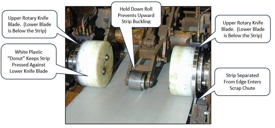
Pickle Lines routinely side trim a large proportion of their output – especially in the case of products designated for cold rolling.
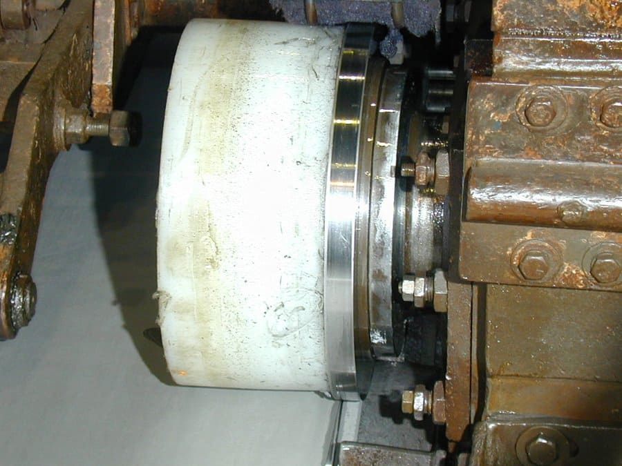
The trimming process involves a “scissoring” action between two rotating circular knives. The knives may be driven – but often operate simply using strip tension in a “pull through” mode. (There may be tension bridles installed directly before and after the trimmer unit which facilitate this.)
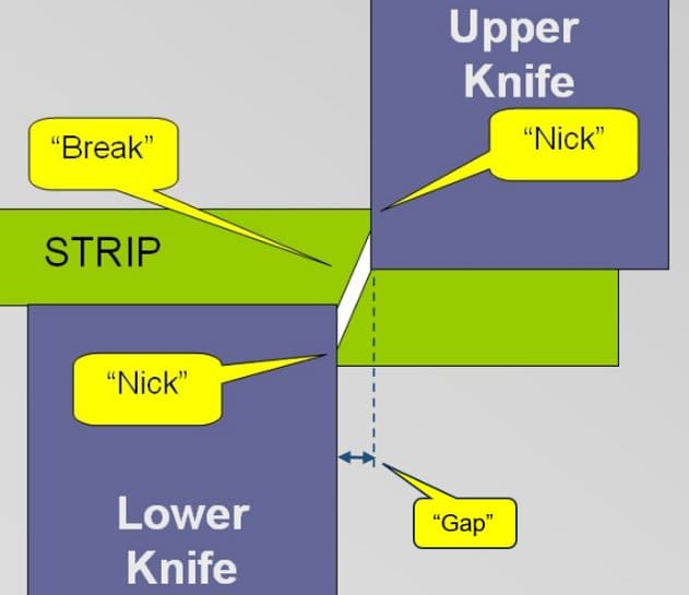
In either case, it is critical that the knives are sharp and have correct horizontal separation distance. This is called the “Gap” – and is defined in Fig. 2a below.
Correct knife gap changes for different products. It should be approximately 8% of the strip thickness – and therefore varies with this dimension. Gap also varies depending on steel grade – less for softer products – and more for harder products. Some approximate / indicative numbers are given in Table 1 below. Modern lines have “driven wedge” or similar adjustment mechanisms capable of changing gap settings to specified values for different products while the line remains in operation.
| Steel Grade | 1.5–2.0 | 2.0–2.5 | 2.5–3.0 | 3.0–3.5 | 3.5–4.0 | 4.0–4.5 | 4.5–5.0 |
|---|---|---|---|---|---|---|---|
| Medium Carbon Steel | 0.14 | 0.18 | 0.24 | 0.28 | 0.32 | 0.36 | 0.42 |
| Soft Steel | 0.11 | 0.11 | 0.12 | 0.14 | 0.16 | 0.18 | 0.22 |
Strip thickness and knife gap values shown in mm.
With gap set correctly, sharp knives will create a small and bright “nick” region approx 25% of the strip thickness. The remainder of the strip will then “break” directly to the corner of the opposing knife. (An important feature of this process is that the break always occurs at an angle close to 7 degrees.)
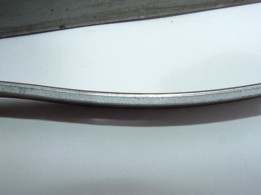
Looking at the cut edge of the strip in Fig. 2b we see a good cut characterised by…
- A shiny penetration zone (“nick”) which extends about 25% of the way through the strip thickness. (More for soft materials, less for hard materials.)
- A darker coloured fracture (break) extends over 75–80% of the strip thickness.
- The line which delineates the above two zones is relatively straight.
- There is little shear burr at the bottom edge of the cut.
A second knife position parameter is vertical knife overlap – often referred to as just “Lap”.
It is the extent to which the knives overlap – when in their fully engaged position.
Vertical “Lap” is less critical than the horizontal “Gap” setting – but is still important.
Lap is kept to the minimum level needed to reliably achieve trim separation. Too much lap increases the difference in lineal speed between the knife and the strip at their point of contact – with the result that heat is generated and wear is increased due to sliding friction.
As is the case with Gap, optimum Lap varies with steel thickness and grade. It is substantially negative in the case of thin products, and slowly increases to become moderately positive with thick strip.
2. Knife Gap Too Tight: Edge Characteristics and Product Issues
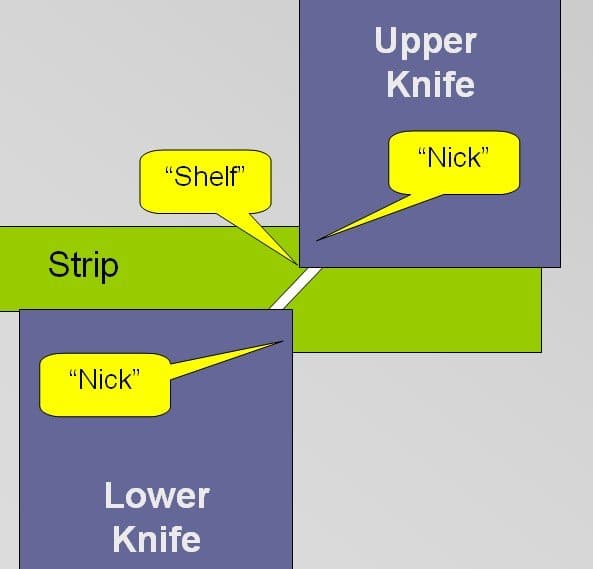
If the knife gap is set too tight, then the “nick” increases in size and the break does not extend from knife edge to knife edge. (Remember the break is always at about 7 degrees.)
This leaves a “shelf” – which is smeared over by further blade intermesh – generating metal debris resembling iron filings. This also makes the line which delineates the two zones irregular. Force, temperature and knife wear all increase considerably. Metal deformation decreases strip ductility in the near edge region – increasing susceptibility to serrated edge defect during Cold Rolling.
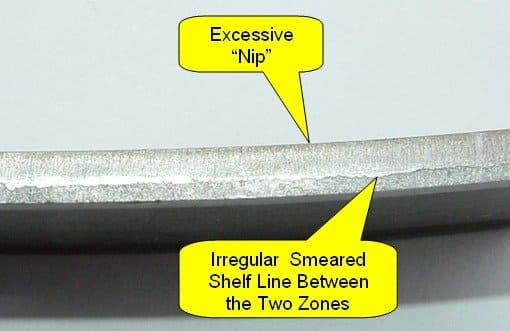
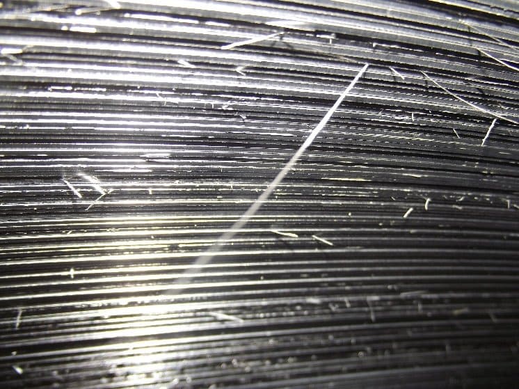
In severe cases long pieces of “shelf” separate – with a few of these remaining partly attached and visible on coil walls.
3. Knives Set Too Far Apart: Multiple Serious Problems
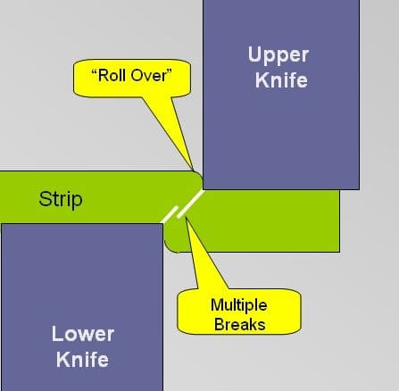
When there is excessive knife “gap”, breaks initiate from the knife corners – but do not meet. The centre part of the strip then tears rather than shearing.
Force and knife wear increase substantially and there is pronounced “Roll Over” or rounding off the top surface of the strip. Other features of an excessive gap condition include…
- A minimal “Nick” or penetration zone.
- A severe burr on the bottom of the strip.
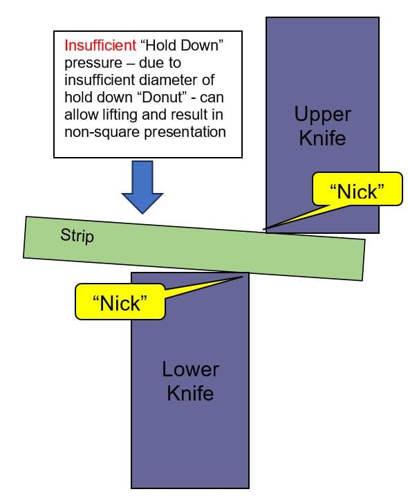
- “Flattening” deformation of the bottom surface close to the cut. (More evident with soft grades and especially if there is insufficient hold down pressure applied by plastic “donuts” – which are not adjustable for product thickness.)
- Possible multiple breaks which can give the appearance of centre lamination. (This is more of an issue with Heavy Gauge.)
Shear cuts made with excessive gap are more likely to generate serrated edge during Cold Rolling.
This is because the tearing / roll over action severely deforms the steel microstructure in the near edge, hardening it and reducing ductility.
This situation is exacerbated if insufficient hold down of the strip against the lower knife allows “flattening” deformation of the bottom edge to occur in the proximity of the cut.
The following Fig. 6 image illustrates both of the above conditions.
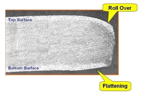
The combination of roll over of the top surface and flattening of the bottom surface can reduce strip thickness at the edge by more than 30%.
If the first Cold Mill rolling pass is less than 30%, the strip edge will not contact the work rolls. Edge extension will then occur as a result of an extremely high concentration of tension stress in this region. This is a major cause of “Serrated Edge” – which is also sometimes called “Saw Tooth Edge”.
A “Serrated Edge” strip is characterised by irregular and widely opened cracks – creating a jagged or broken appearance.
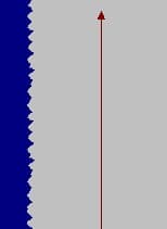
Serrated edge material is prone to break in the entry section of the Galvanising Line – where serrations concentrate stress and serve as initiation points for transverse tearing. This situation is exacerbated if serrated edge is combined with a cambered or full centre shape condition, which concentrates strip tension required by the line into the strip edge region. (Conversely, a wavy edge shape condition concentrates line tension stress in the strip centre region, thereby reducing the likelihood of transverse strip tearing.)
Galvanising Line Entry Section strip breaks may cause extended operating delays if they require the Furnace to be re-threaded.
The presence of even slight edge serration on Galvanised product is especially problematic for Paint Lines. This is due to the damage it causes to paint application rolls, resulting in edge bead defects.
In summary, serrated edge is caused by poor trimmer setup in the Pickle Line. However it does not manifest until the Cold Rolling Mill – and does not cause substantial problems until it reaches Galvanising and Paint Lines.
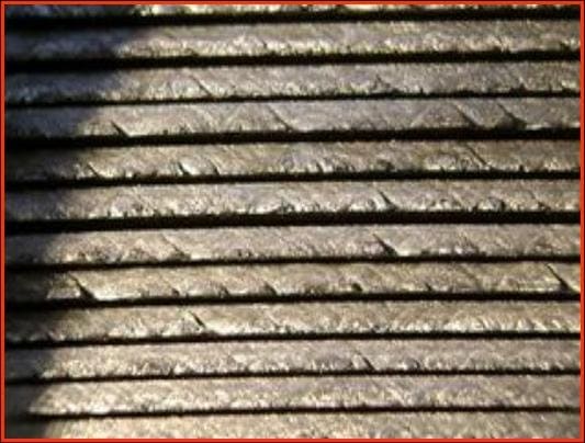
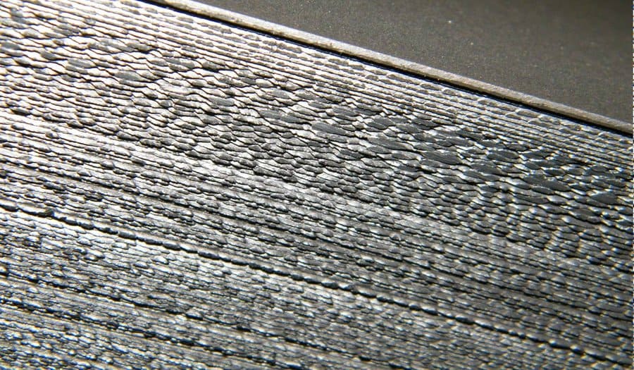
It can be useful to examine side walls of cold rolled coils – to detect mild cases of serrated edge and correct them before more serious problems develop. As shown in Fig. 8 below, serrations start with the formation of 45 degree slip lines – which then begin to crack apart and separate. Some form of magnification is useful when performing these checks. Fully developed serrated edge on coil walls involves further separation – and is impossible to mistake.
4. Strip Hold Down Pressure
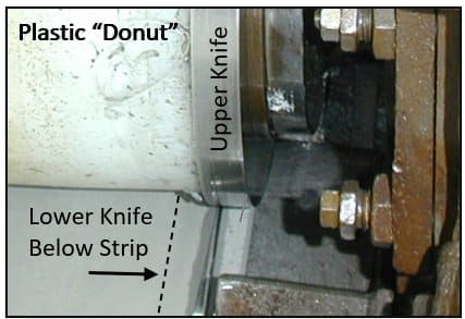
Side Trimmer upper circular knives are mounted on central shafts – with slightly smaller diameter plastic tubes mounted next to them. The purpose of these tubes is to hold the strip down against the lower knife blade underneath. Because of their general physical dimensions and often white colour, North American Operators frequently refer to them as “Donuts”.
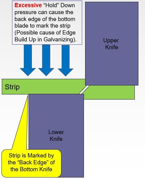
Too much or too little hold down pressure causes problems. Unfortunately, diameter of the plastic hold down has to be selected as a best compromise for the thickness range of strip being processed. (Ideally, radius of the plastic would be less than radius of the top trimmer knife by an amount equal to the thickness of the strip.)
5. Conclusions
Pickle Line Side trimmer setup is very important – and often not sufficiently well recognised or understood.
Having a correct knife gap – appropriate for the product thickness and strength level – is critical for determining whether the strip shears cleanly and well. Sharp knives and good strip hold down are important too.
Knife Gap is a product group specific setting – requiring to be adjusted accordingly. Adjustments can be minimised by scheduling appropriate similar materials together. Equipment with capability to make these adjustments while the line continues operating is a major advantage.
More importantly, a poor side trim can later cause development of Serrated Edge in the Cold Mill. This is unacceptable to customers – plus it contributes to strip breaks in Galvanising Lines.
Serrated edge on Galvanised product is also notorious for damaging Paint Line applicator rolls and thereby causing edge bead defects.
There is a substantial time lag – and multiple operating plants – between root cause and visible serious failure. This makes side trimmer setup easy to under-prioritise and expensive to get wrong. Pickle Line samples should be regularly and rapidly assessed against established criteria. And side walls of Cold Mill coils can be inspected for the presence of early-stage 45 degree slip lines.
Next Steps for Your Business
Correct side trimmer knife gap and hold-down setup can deliver significant, fast-payback benefits across your line, including:
- Fewer serrated edge defects reaching the Cold Rolling Mill
- Reduced strip break risk and re-threading delays at the Galvanising Line entry
- Fewer edge bead defects and less applicator roll damage on Paint Lines
- Longer knife life and reduced debris accumulation in the Pickle Line
If you are reviewing side trimmer performance or investigating recurring serrated edge complaints, why not give us a no-obligation call? Our experts will be pleased to discuss your requirements with a view to an initial concept study.
152 projects in 48 countries since 2001
Free, confidential first conversation No obligation Reply within one working day

| Temper Rolling & Tension Levelling | Strip shape principles, tension levelling and temper rolling equipment, discontinuous elongation and surface conditioning of zinc-coated strip. |
| Dross Control in Zinc Galvanising Lines | Dross formation, composition and cost in zinc galvanising lines, including top and bottom dross mechanisms and removal practice. |
| Coil Winding in Galvanising Lines | Radial and tangential stress in wound coils, strip compressibility, telescoping and other winding failure modes and corrective actions. |
| Air Knife & Coating Mass Control | X-ray coating mass measurement, ASTM specifications, air knife design and setup, edge baffles and automated coating weight control. |
| Plate Mill Yield and Provisioning | Provided yield and provisioning, yield cost and margin loss, plan view rolling, scale loss and hydraulic gauge control in plate mills. |
| Strip Centring in Vertical Furnaces | Roll crown mechanics, the balance between tracking-off and heat buckle, ground crown profiles, roughness and thermal crown control in vertical furnaces. |
How to Cite This Article
Hesling, S.W. (2026) 'Side Trimming in Steel Pickle Lines: Knife Gap and Serrated Edge', SteelOnTheNet Technical Reference Series. Available at: https://www.steelonthenet.com/resources/technical/side-trimming-pickle-lines.html (Accessed: 26 October 2026).
This article is based on original technical material by Steven W Hesling, published by Metals Process Solutions Ltd, and is reproduced on SteelOnTheNet with the author's permission. The document was written entirely by the author – not by AI – with minor edits only by SteelOnTheNet.