Crown & Tracking Control
Published:
This technical module covers strip centring in the large vertical furnaces used by automotive galvanising and continuous annealing lines. It examines how ground and thermal roll crown are utilised to maintain strip tracking on the centreline, and how this mechanism is managed to limit the risk of heat buckle with thin products, and off-tracking of thick and narrow products. It forms part of a series of galvanising line technical reference modules authored by Steven W. Hesling.
1. Introduction
Every continuous process line needs a reliable means of keeping strip centred on its transport rolls. Early industrial belt-and-pulley drives solved an analogous problem, using a crowned pulley profile that naturally centred the belt. Transferred to ground roll crown, this same principle provided a simple and inexpensive “passive” strip centring mechanism in early galvanising lines.
Most modern process lines now use active strip centring. This involves transverse strip position sensors combined with rolls mounted on moveable frames. Depending on the frame configuration, these are capable of stepping strip sideways, directing it at a forward angle, and even steering backwards into a preceding span. This achieves a substantial improvement in centring performance, but it cannot be applied everywhere. Automotive lines have large furnaces with long vertical spans, and roll bearings in these furnaces must be mounted in cold locations outside the furnace shell, with shafts sealed to prevent air from entering the controlled atmosphere inside. Engineering active steering hardware under these conditions is impractical.
Vertical furnaces on automotive lines therefore still rely on roll crown for strip centring. Doing this well is genuinely difficult, given the wide range of strip sizes, mechanical properties and furnace temperature conditions that automotive products demand. A single furnace may be required to run everything from thick, narrow, high-strength product to thin, wide, very soft exposed-panel steel — and the crown profile ground into the rolls has to serve that entire product range.
This is complicated further by the fact that the rolls themselves are not fixed-geometry components. Their total crown changes continuously, as thermal expansion adds to or subtracts from the ground profile, depending on each roll’s transverse temperature variation. Strip centring in a vertical furnace is therefore not a one-off design issue resolved at the roll grinding stage. It is an ongoing operational balance between ground crown design, roll surface condition, thermal history and incoming strip shape.
This module explains how roll crown generates strip centring force, and the risks involved if that force is too much or too little. It then reviews practical technologies and methods that extend the safe operating window over which crowned rolls can be used effectively.
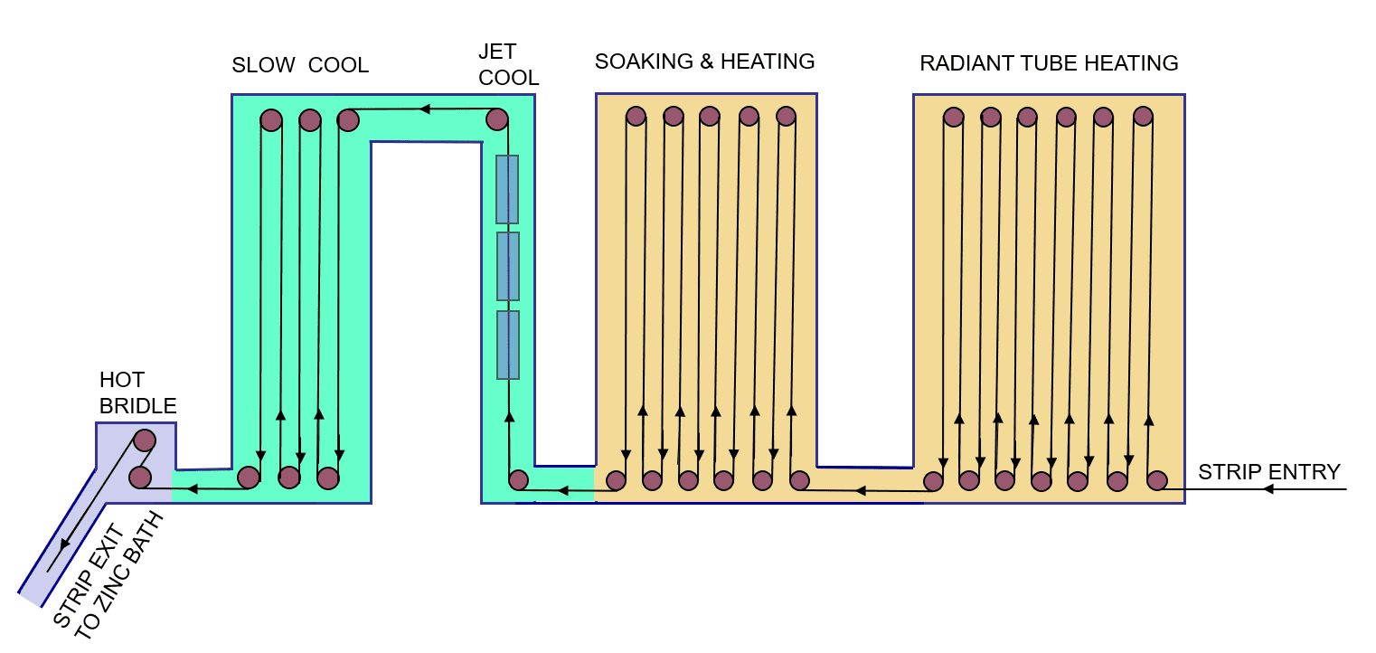
Figure 1 above shows a generic layout of a vertical galvanising line furnace. Depending on the actual products made, equipment items may be added or altered — but the sequence shown above is normally followed.
The name “vertical” derives from this being the primary direction of strip travel in the furnace. Vertical spans are typically 20 metres or more. Having many of these results in extended furnace residence times and corresponding process opportunities.
2. Roll Crown: Definition and Sources
In metals industry process lines, “roll crown” refers to transverse variation in roll diameter — which is normally close to symmetrical about the roll centreline. Because the two edge diameters can differ slightly, their average is used in the crown calculation. By convention, crown is positive when the centreline diameter exceeds the edge diameter, and negative when the centre diameter is smaller than the edges.
Crown = C − (E1 + E2) / 2
(% Crown = 100 × Crown / Average Diameter)
where C is the centreline diameter and E1, E2 are the two edge diameters.
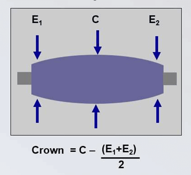
There are two distinct sources of roll crown, and the distinction matters a great deal for how centring works in practice:
- Ground crown — a physical diameter variation imparted during roll grinding, which remains essentially constant over an extended period.
- Thermal crown — caused by thermal expansion of the roll. This requires a transverse temperature variation to exist within that part of the roll which contacts the strip. Because it depends on heat input, thermal crown can vary substantially, and quickly, whenever operating conditions change.
3. How Crowned Rolls Centre the Strip
Crowned rolls direct both sides of the strip towards the roll centreline. When strip is centred, the two halves exert equal and opposite transverse forces, so the net transverse force is zero. If the strip drifts off-centre, more of it sits on one side of the centreline than the other. This generates a transverse force imbalance — a restoring force that pushes the wider side back towards the centre.
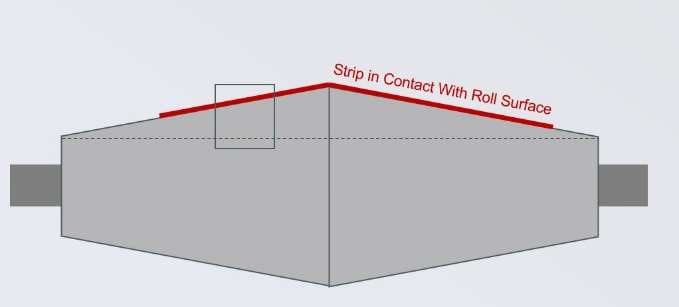
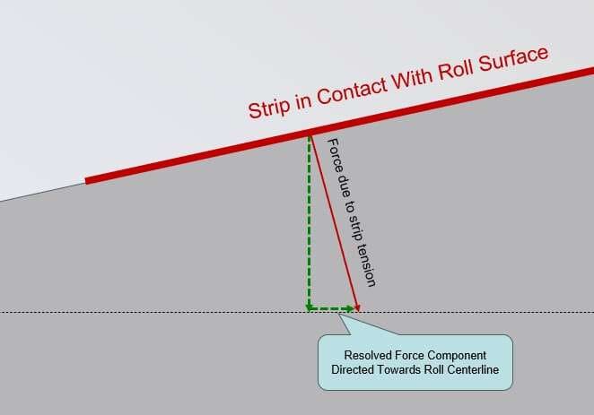
Three variables govern the magnitude of this centring force:
- Centring force increases with roll crown, which can be ground, thermal, or a combination of these two.
- Centring force increases with strip tension.
- Centring force increases with strip width.
This last relationship is the source of most of the practical difficulty covered in this module. The roll crown needed to keep narrow strip reliably on-track can, when applied to wide and thin strip, generate more centring force than the strip can mechanically withstand without buckling.
4. Strip Centring-Related Issues
Vertical furnace centring problems fall into two opposing categories, and furnace roll design is fundamentally an exercise in balancing them.
Insufficient Centring Force: Tracking-Off
Where centring force is too low, strip can drift away from the roll centreline until it contacts furnace equipment, possibly causing severe damage. This typically affects narrow strip.
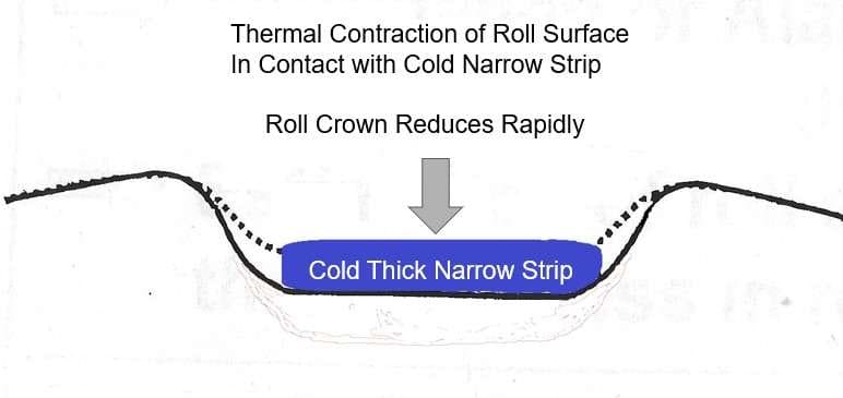
Thick, narrow strip may introduce a further complication: it can rapidly chill the centre of furnace rolls during start-up, line speed changes, or if a furnace heating zone trips out. This locally cools the roll, inputting negative thermal crown and rapid, unpredictable off-tracking.
Excess Centring Force: Heat Buckle
At the other extreme, wide strip generates high centring force, and if that strip is also thin and soft, its mechanical buckle limit can be exceeded. The result is a longitudinal “heat buckle” developing near the strip centre. Published studies indicate buckles initiate while the strip is still in contact with the roll, then intensify once the strip separates from it. Heat buckle can cause strip breaks that, in large vertical furnaces, normally take several days to repair. Upper rolls are more susceptible to this failure mode than lower rolls, because strip weight increases tension at the top of the furnace span.
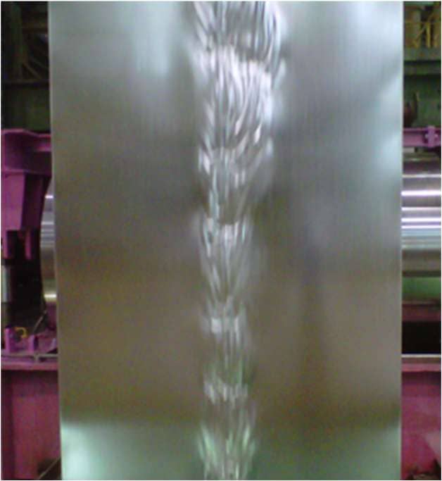
The product most commonly affected by heat buckle is Interstitial Free (IF) steel, widely used for horizontal exposed automotive panels such as hoods, roofs and trunk lids. IF steel is high value and combines several buckle-promoting characteristics. It is very soft, and made using a high furnace temperature, which softens it further in the furnace. It is also moderately thin at around 0.65–0.80 mm (occasionally down to 0.5 mm), and also very wide, particularly when supplied for large North American vehicles.
Blanks for press-formed automotive panels carry a 50 mm hold-down allowance on all edges, which is later discarded — so IF strip must be significantly wider than the panel it will be used to make.
Being unusually wide compounds the problem in a second way: there is little suitable wider product available to schedule ahead of IF. This matters, because generating a favourable (zero or negative) thermal roll crown ahead of buckle-sensitive product requires transitioning down from something wider.
Buckling Index = Width / Thickness
Example: 1725 mm wide strip at 0.5 mm thickness → 1725 / 0.5 = 3,450
Modern galvanising lines — with appropriate product sequencing and furnace roll crown profiles — should be capable of running carbon steel grades up to around a 3,500 buckling index at moderate furnace temperature.
Four methods are used to extend the safe operating window between these two failure modes:
- Complex multiple-angle ground crown profiles
- Increased roll roughness in the buckle-critical central region
- Control of thermal roll crown to complement ground crown
- Management of incoming strip shape (flatness) from the cold rolling mill
Each of these is examined in turn below.
5. Compound Ground Crown Profiles
Hot and cold rolling mills normally use a progressive (sinusoidal) crown profile, to compensate longitudinal roll bending under heavy rolling loads. This is the profile most people picture when roll crown is mentioned.
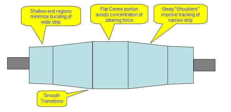
But vertical furnace rolls instead use a very different compound profile, combining several distinct taper angles across the roll face rather than a single smooth variation.
Each zone of the profile in a vertical furnace roll serves a specific function:
- A flat centre region avoids tapered sections meeting directly, which would otherwise concentrate steering force at the centreline.
- A steep shoulder immediately adjacent to the flat centre improves tracking of narrow strip by supplying strong centring force close to the centreline.
- A shallow-angle region near the roll ends limits centring force for wide strip, reducing buckle risk.
Transitions between these angled zones are curved, using an appropriate radius rather than a sharp change in taper angle. Sharp transitions themselves promote local buckling, as a step change in taper angle concentrates transverse stress at this location.
The underlying mechanics of this were established by Kawasaki Steel. Its 1984 technical report combined finite element stress analysis, physical simulation using aluminium foil, and full-scale trials on a commercial continuous annealing line[1].
The study explained why roll crown, while essential for correcting strip “snaking”, simultaneously imposes non-uniform tension across the strip width and generates the compressive membrane stresses that cause buckling. It confirmed the relationship set out above: buckling susceptibility increases with strip width, and decreases with the width of the roll’s parallel (flat) centre section. The compound, multi-taper ground crown profile described above, with its smoothed transitions, remains the practical embodiment of these findings on modern furnace rolls.
6. Roll Surface Roughness in the Flat Centre Region
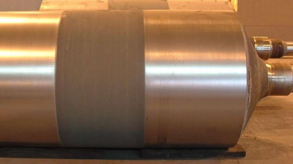
Buckle resistance is improved by the flat centre region described above, which avoids opposing centring forces meeting directly at the roll centreline. That effect is further enhanced when the flat region is finished with a rougher surface than the rest of the roll. This is most likely because increased friction restricts transverse strip movement; it may also reduce longitudinal slip of low-tension thin strip across the roll surface.
Reported roughness values illustrate the scale of the difference: around 8.0–10.0 µm Ra in the flat centre region, compared to roughly 0.8 µm Ra on the shoulders.
7. Thermal Roll Crown: Development and Control
Thermal crown can be very significant. Whether it is positive or negative depends on the temperature differential across the part of the roll surface in contact with strip — commonly a legacy of previously running strip of a different width and temperature.
If strip is hotter than the roll, then progressively wider strip generates more thermal crown, which increases buckle risk in thin, wide strip while reducing tracking-off risk in thick, narrow strip. A negative thermal crown does the opposite: it reduces buckle risk in thin, wide strip, at the cost of increased tracking-off risk with thick, narrow strip.
This relationship is put to deliberate use in production scheduling. To minimise buckle risk with thin, hot, wide, buckle-sensitive product, mills schedule several coils immediately beforehand that are both wider and thicker than the sensitive product, with a peak metal temperature equal to or greater than it. This creates roll temperature conditions which help when the buckle-susceptible IF material arrives.
Japanese lines have taken this further, using furnace rolls fitted with embedded thermocouples to continuously measure roll temperature profiles. This data is combined with strip temperature readings from pyrometers and fed into real-time tracking models that anticipate centring behaviour rather than reacting after the issue is observed to be developing.
This forward-looking capability matters because a roll’s temperature profile reflects an accumulated thermal history across several preceding coils, not just the coil currently passing over it.
Two further technologies have been developed to actively manage thermal crown, though neither has been adopted widely:
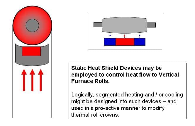
- Heat shield devices with internal cooling, and potentially heating, have been proposed to modify heat flow into upper furnace rolls. This could logically be extended to include segmented heating or cooling for proactive thermal crown control, but it remains a complex technology that has not been widely implemented.
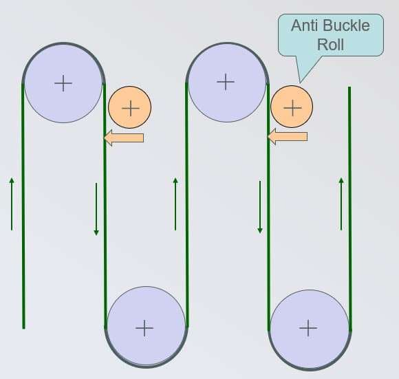
- Anti-buckle rolls, positioned immediately after upper furnace rolls, were proposed by Kawasaki Steel and successfully installed at the Florange continuous annealing line. This has likewise not become common, most likely because of cost, complexity and maintenance issues.
8. Incoming Strip Shape (Flatness) from the Cold Rolling Mill
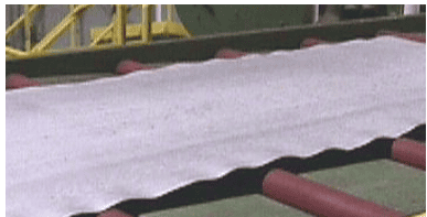
Strip from the cold rolling mill may display edge waves and centre buckles as it is unwound at the entry end of the line. Another, less common possibility is “quarter buckles” — occurring approximately half way between the edge and centre of the strip.
These are all the result of transverse variation in strip length — for example, edge waves occur when the edges are longer than the centre of the strip. The recognised technical term for this is “shape”, but “flatness” is more descriptive and sometimes also used.
Line bridles impart a specified total strip tension, but where shape deviations exist, that tension does not distribute evenly across the strip width. Specifically, there is zero tension in regions where buckles or waves exist, and increased tension in the remaining parts of the strip.
These strip tension conditions interact with roll crown to affect furnace centring in different ways. For example, edge waves on both sides decrease the effective width of the strip and increase local tension in the central region. Also, a single wave on one edge of the strip creates an uneven force distribution, which pushes the strip towards the wave side of the line.
Modern cold rolling mills have shape measurement and control systems, so it is possible to order a shape condition that is beneficial for a specific product. For example, a moderate quarter buckle in incoming cold-rolled IF strip can decrease issues with heat buckle, by reducing the tension-related force generated by the steeply angled section of the roll at this location.
| Shape from Cold Mill | Centring Outcome | Comment |
|---|---|---|
| Flat | Good | Best condition; centring functions as intended. |
| Small edge wave – both sides | OK | Centring force changes slightly. |
| Large edge wave – both sides | Marginal | Substantial change in centring force, depending on edge wave dimension versus roll segment dimension. |
| Small centre wave | Marginal | Furnace buckle promoted, especially with thin, wide product. |
| Large centre wave | Bad | Furnace buckle will easily occur with thin, wide product. |
| Large edge wave – one side only | Bad | Mis-tracking towards the wave side is promoted. |
Because incoming cold mill shape has this direct effect on furnace centring, flatness control at the cold rolling mill is properly considered part of the same overall system, not an unrelated upstream process.
9. Conclusion
Strip centring in vertical galvanising furnaces is fundamentally a balancing act. Roll crown — ground and thermal — generates the transverse force that keeps strip on-centreline, and that force varies with crown, tension and strip width. Too little force and narrow or thermally chilled strip drifts (“snakes”) off-centre and risks contact damage. Too much force and wide, thin, soft product such as IF steel exceeds its buckle limit and develops heat buckle, with the potential for a furnace strip break and consequent extended operating delay.
No single measure resolves this trade-off; the practical solution is a combination of complementary techniques. Compound ground crown profiles — flat centre, steep shoulder, shallow end region, smoothly blended — give each part of the product range an appropriately tuned baseline centring force. Increased roughness in the flat centre region adds buckle resistance without decreasing crown.
Thermal crown, managed through deliberate product sequencing and, on more advanced lines, real-time thermocouple and pyrometer-driven tracking models, allows strip centring behaviour to be shifted. And because incoming strip shape from the cold rolling mill can itself distort the centring force distribution, shape/flatness control in the cold mill is an integral part of this system rather than a separate concern.
None of these four measures resolves the trade-off on its own — a vertical furnace line which treats any one of them as a fix, rather than as one lever among four, will eventually find its operating window narrower than an automotive product range requires.
References
- Sasaki, T., Hira, T., Abe, H., Yanagishima, F., Shimoyama, Y. and Tahara, K. (1984) 'Control of Strip Buckling and Snaking in Continuous Annealing Furnace', Kawasaki Steel Technical Report, No.9, pp.36–46. Direct PDF (hosted by JFE Steel, successor to Kawasaki Steel): https://www.jfe-steel.co.jp/archives/en/ksc_giho/no.09/e9-036-046.pdf
This module also draws on the author's direct process experience with furnace roll design and thermal crown management, in North American, European and Asian galvanising operations.

| Temper Rolling & Tension Levelling | Strip shape principles, tension levelling and temper rolling equipment, discontinuous elongation and surface conditioning of zinc-coated strip. |
| Air Knife & Coating Mass Control | X-ray coating mass measurement, ASTM specifications, air knife design and setup, edge baffles and automated coating weight control. |
| Coil Winding in Galvanising Lines | Radial and tangential stress in wound coils, strip compressibility, telescoping and other winding failure modes and corrective actions. |
| Dross Control in Zinc Galvanising Lines | Top and bottom dross formation mechanisms, aluminium control, removal practice and cost reduction in the galvanising bath. |
| Plate Mill Yield and Provisioning | Provided yield and provisioning, yield cost and margin loss, plan view rolling, scale loss and hydraulic gauge control in plate mills. |
| Side Trimming in Steel Pickle Lines | Side trimmer knife gap setup and resulting cut edge characteristics, defects from incorrect knife gap, hold-down pressure and how poor trimming causes serrated edge. |
How to Cite This Article
Hesling, S.W. (2026) 'Strip Centring in Galvanising Line Vertical Furnaces', SteelOnTheNet Technical Reference Series. Available at: https://www.steelonthenet.com/resources/technical/strip-centring-vertical-furnaces.html (Accessed: 7th October 2026).