Provisioning & Rolling Control
Published:
This technical module covers yield engineering in steel plate mills: how "provided yield" is calculated, what yield loss actually costs and the process control techniques – from slab preparation through to plan view rolling and hydraulic gauge control – used to manage it. It forms part of a series of technical reference modules authored by Steven W Hesling.
1. Introduction to Plate Mill Yield
Plate mills typically comprise one or two reheat furnaces and one or two reversing rolling stands, with water cooling commonly fitted for thermo-mechanical controlled processing of advanced grades. Downstream equipment includes roll intermesh flatteners, side and end trimming, identification marking and extensive transfer systems including cooling tables. These mills produce discrete flat plates up to around 20 metres long and 3.5 metres wide – longer lengths are technically possible but rarely viable given road and rail transport limits – with typical mill capacity in the range of 700,000 to 1,000,000 tonnes per year. Overall yield is typically 86–92%.
Steckel mills also produce plate, in two distinct ways. Many roll 96-inch (2.4 m) wide coils in plate grades and thicknesses – a width Hot Strip Mills cannot reach – which are then levelled and cut to length for flat plate applications. This "plate in coil" route is considerably more efficient than rolling individual flat plates on a conventional plate mill. Alternatively, a Steckel mill can bypass its winding furnaces and downcoiler to roll flat plate directly above its normal coiling width limit, in which case it behaves much like a conventional plate mill and is subject to the same yield issues.
A defining feature of plate mills is their ability to rotate a slab through 90 degrees, "cross roll" it out to an aim plate width, then rotate back for final rolling to length and thickness. This cross rolling step is critical to yield: correctly managed, it produces straighter plate ends and edges than would otherwise be achievable, directly reducing the "plan view" trimming losses discussed later in this module.
2. Provided Yield and Provisioning
Plate mills run at substantially lower yield than Hot Strip Mills, and the reason is structural rather than a matter of process discipline. In a Hot Strip Mill, everything except scale and crop loss ends up in a finished coil, and the customer accepts coil weight within a usually generous range. Plate manufacture allows almost no such tolerance: customers specify thickness, width and length within narrow ranges – as defined in EN10029 – and plate weight follows directly from those dimensions and steel density.
This forces Production Planning into an up-front decision known as "providing" or "provisioning": based on the weight of a single plate, or several plates rolled together in a pattern, appropriate slab dimensions and weight are selected. A provided yield of 88%, for example, means the plate weight calculated from ordered dimensions is 88% of the selected slab weight – and this figure represents the best possible outcome for that slab, not a target with headroom either side.
Two things can happen once rolling variability is introduced. If the as-rolled plate carries excess length of prime steel, that excess is simply sheared off into the scrap bin. If it falls short, yield is lost a second way, as the plate is cut back to an alternative, shorter marketable dimension. Either way, provisioning sets a ceiling; process variability only ever erodes it.
3. Yield Cost and Margin Loss
Plate mills and Hot Strip Mills share the same underlying economics when product is lost, even though their yield levels differ substantially.
Real losses are rarely this clean. Around 1% of yield loss typically arises from scale formation during reheating, and scale is sold for well under half the price of scrap. A slab can also be lost partway through conversion – after fuel has been spent reheating it, but before electricity has been spent rolling it – which accounting teams are generally well equipped to handle through standard cost protocols.
A harder loss to quantify, and potentially the larger of the two, is lost profit margin. In the worked example above, a plate costing US$600 per tonne to produce sells for US$1,000 per tonne, giving a contribution margin of US$400 per tonne.
Whether a lost tonne of plate actually costs that margin depends entirely on the business scenario: if the market is large and slab supply is the limiting factor, every lost tonne genuinely represents lost margin. If the market is small and the mill has spare slab supply and rolling capacity, there is effectively zero margin loss – the mill simply rolls and sells a replacement plate.
Establishing which scenario actually applies at any given time is not straightforward: the necessary information can be hard to verify, conditions change quickly and this is not typically a task Accounting has established procedures for.
4. Aggregating Process Variability: The Random Walk Method
Provisioning is, at its core, a variability aggregation problem. If a plate mill had no process variability at all, every plate would come out an identical length, width and thickness, and slab mass could be optimised to deliver exactly the ordered dimensions. In practice, variability across multiple sub-processes combines to produce a Gaussian distribution of finished plate lengths, from which an aim plate length – and a corresponding provided slab dimension – can be established such that under-length plates occur acceptably rarely.
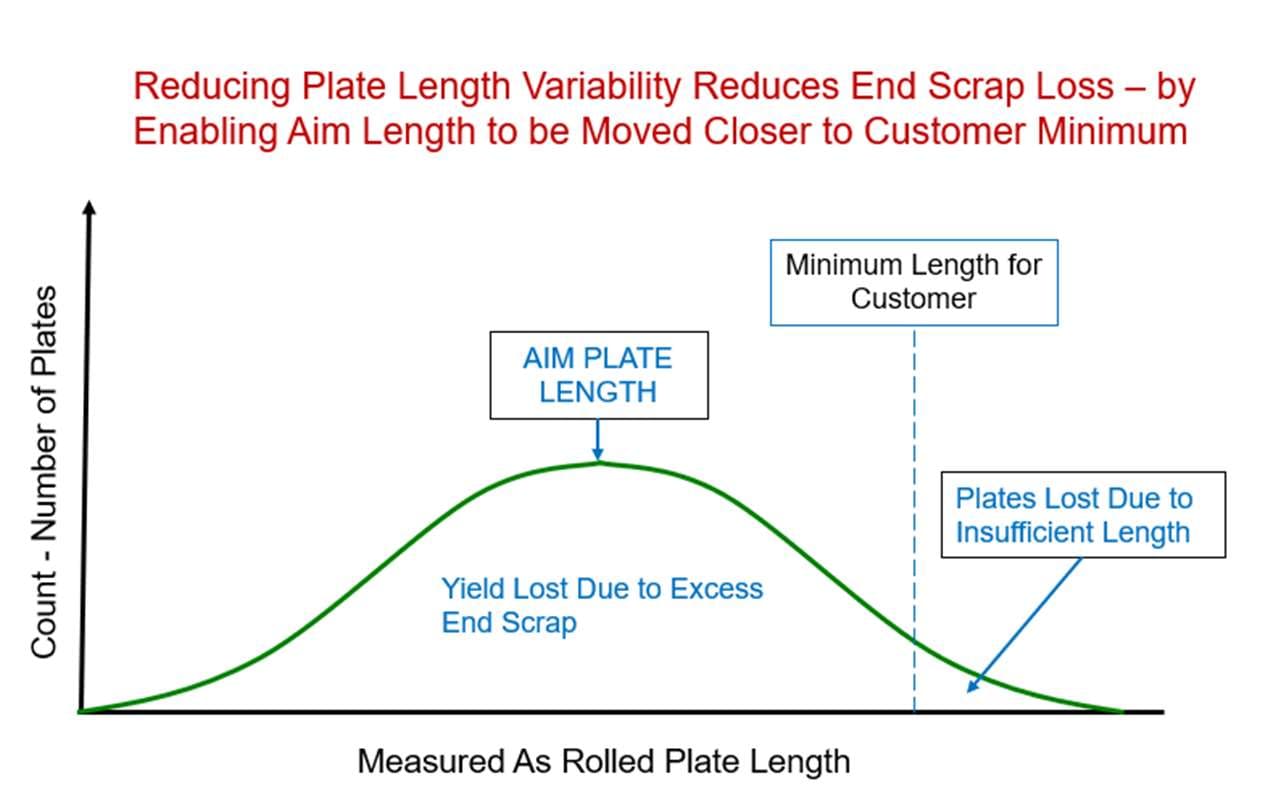
A useful way to picture this is a random walk: a model of a system with multiple successive, independent random steps. Imagine a three-stage construction project – foundations (4 months ±1), structure (7 months ±2) and services (3 months ±1) – where each stage has its own time distribution centred on a nominal value.
We know the minimum, maximum and nominal time for the whole project, but not how total completion time is actually distributed. A random walk resolves this: draw one random completion time from each stage's distribution, add them together, and the result is one valid possible outcome for the whole project. Repeating this many times builds a full Gaussian distribution for total project duration.
The same logic generates a distribution of as-rolled plate length from a plate mill's multiple sub-processes, and can answer genuinely useful operational questions – for example, how much adding one further inch of slab length reduces the probability of producing a short, below-minimum plate.
5. Processes Contributing to As-Rolled Length Variability
5.1 Incoming Slab Dimensional Accuracy
Continuously cast slabs normally have good width and thickness accuracy, but length is a weaker point. Length error is driven largely by the positioning and initiation accuracy of the two oxy-fuel cutting torches – one on each side of the slab – which move in unison to make a transverse edge-to-centre cut. On a Hot Strip Mill, slabs are long enough that a given absolute length error is a small percentage of total length and has negligible effect on coil weight. Plate mill slabs are much shorter, so the same absolute error becomes a far larger percentage.
Mills manage this in two main ways. Operators can regularly measure randomly selected yard slabs against ordered length – this does not improve accuracy, but it monitors offset and distribution and guards against surprises. Alternatively, mills can receive longer "HSM-length" cast slabs and cut them accurately to the required plate mill lengths in the yard, using oxy-acetylene torches mounted on slow-moving carriages. Done carefully, this spreads a single Caster length error across multiple plate mill slabs rather than concentrating it in one, and can also reduce required slab inventory and support small-quantity specialty orders cut from long master slabs.
5.2 Scale Loss
Almost all scale loss in plate mills occurs in the reheat furnaces, typically in the range of 0.9–1.4%. Control follows similar principles to Hot Strip Mill practice: the final high-temperature soaking zone before extraction runs a fuel-rich combustion atmosphere to limit rapid scale growth, with the atmosphere shifting to air-rich further back towards furnace entry. Too much excess fuel in the soak zone, however, can make scale harder to remove in the primary descaler downstream – and difficulty of removal is also influenced by steel chemistry, which is why some highly alloyed grades are sprayed with a water-based ceramic coating before entering the furnace.
Rolling delays increase scale loss directly, since hot slabs sit waiting in the furnace longer than required. Occasionally a slab already extracted from the furnace cannot be rolled and must return to the yard, incurring a second scale loss when it is eventually reheated – which raises the risk of a short plate on that particular slab, with no real alternative but to roll it and accept the outcome.
5.3 Plan View Rolling
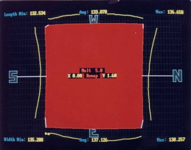
Plan view rolling is arguably the most consequential yield lever in a plate mill, and the most technically involved. Its objective is straightforward: produce an as-rolled plate as close to rectangular as possible, minimising the end and edge trim otherwise required. The discussion below applies to the 8.0–9.5 inch (203–241 mm) slab thickness range now typical – historically some mills used slabs up to 12 inches thick to satisfy minimum reduction ratio requirements for closing internal casting porosity, but process improvements have largely removed that constraint.
Most plate is rolled width-from-width ("broadside" rolling): the slab is rotated 90 degrees, cross-rolled to plate width, then rotated back. Rolling plate width from slab length is technically viable but less common, partly because it risks exposing slab centreline defects along both edges of the full plate length.
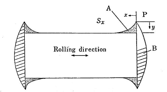
As a bar passes through a rolling stand, some width spread always occurs, but spreading is substantially greater very close to the bar ends. This happens because as bar ends enter the mill there is a brief transient condition where nothing on the far side of the roll bite restricts sideways movement. A 9.5-inch slab rolled down to 5.0 inches, for example, has been observed with ends 2.6 inches wider than the plate body – and these ends can bulge unevenly top-to-bottom, reflecting uneven furnace heating or a roll bite positioned slightly above pass-line to avoid bar end "turn-up".

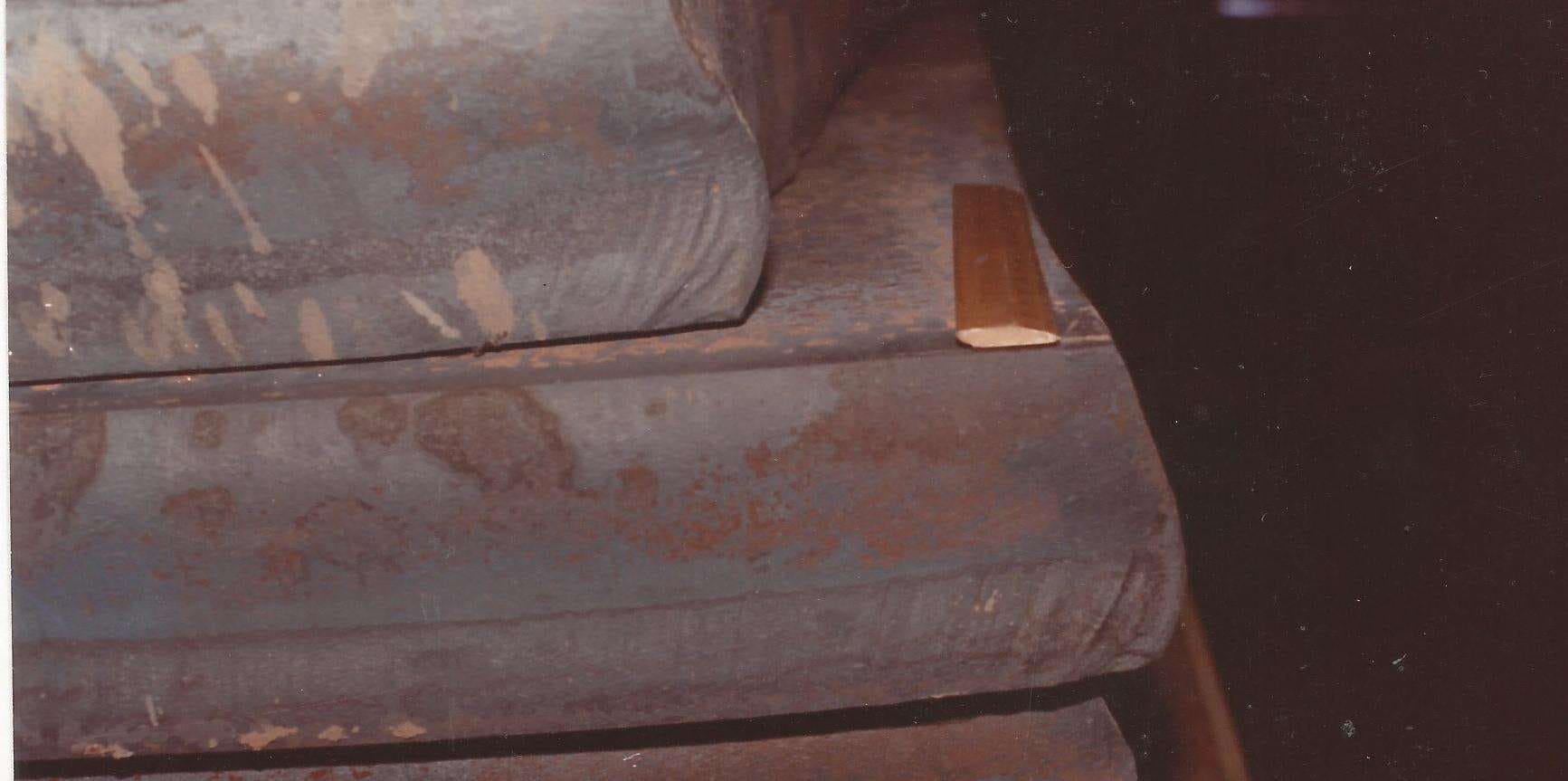
Longitudinal rolling (length as the rolling direction) produces this plan view effect; cross rolling (width as the rolling direction) produces a similar effect displaced by 90 degrees. Because the two directions distort plan view in opposing ways, correctly balancing reduction between them makes it technically possible to achieve a plate close to rectangular – though a slight concave edge is sometimes deliberately preferred in practice, to guard against longitudinal camber. Earlier passes, taken while the bar is still relatively thick, have a greater plan view effect than later ones.
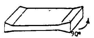
Mills fitted with hydraulic screw-down capsules can roll deliberate thickness variation along a bar's length – commonly rolling extra thickness into both ends during the last pass before turning, known as "dog bone" rolling for the resulting profile's resemblance to a bone. After the 90-degree turn, this extra end thickness produces further edge extension and a meaningfully improved plan view; Japanese plate mills pioneered the technique as far back as the late 1980s. Edging rolls can also be fitted and can help, though they are harder to operate successfully than Hot Strip Mill edging rolls, partly due to the short length of plate mill slabs.
More recently, Japanese mills have increasingly paired these physical rolling techniques with predictive models and machine vision or AI – industrial cameras capturing plan-view images of both the intermediate bar and finished plate, enabling real-time corrective action from predicted and measured plan view together.
5.4 Rolled Width Control and Hydraulic Automatic Gauge Control
Modern plate mills are extensively automated. Before a slab is even charged into the reheat furnace, a process computer pre-calculates the entire rolling programme – number of passes with aim thickness, width and length targets for each; turning points in the pass sequence; rolling load and motor power checks; rolling speed and pass duration; and metal temperature per pass, including inter-pass cooling where thermo-mechanical controlled processing is required – to confirm the mill can achieve the required dimensions within a defined temperature trajectory. Within this scope, width and thickness control matter most for realised yield.
Modern mills use imaging systems to measure bar dimensions accurately, including one pass before the final width pass is completed – data that can be used to correct final width.
Hydraulic Automatic Gauge Control (HAGC) uses fast hydraulic actuators to adjust work roll gap. Rolling force stretches the mill housing elastically, and any change in that force otherwise shows up as a change in product thickness.
The foundation of modern AGC is the BISRA principle, developed by the British Iron and Steel Research Association: hydraulic capsules move the roll opening to cancel out housing elongation caused by variation in rolling load.
Feed-forward AGC extends this by using an entry-side thickness gauge to detect an incoming disturbance, tracking its travel time to the roll bite from material speed, and adjusting cylinder position at exactly the right moment to pre-empt it – used, for example, to compensate for skid marks (cold transverse bands left where slabs rested on water-cooled furnace skids, which roll harder and would otherwise cause load and thickness spikes).
Head and tail end compensation addresses a related challenge at the leading and trailing edges of a plate during final passes: a fast increase in inter-roll gap at the trailing edge, applied specifically when rolling thin plate, reduces the risk of metal tearing off at that edge.
6. A Practical Framework for Yield Control
Maximising plate mill yield requires effective control across a genuinely multi-stage process, not a single fix. Estimating yield loss and setting appropriate slab dimensions requires a mathematical method – the random walk approach described above – to aggregate the average and variability of multiple sub-processes into a single distribution curve. Most yield loss itself is associated with side and end trim, removed to reach a rectangular plate meeting customer-specified dimensions. Six areas of control follow directly from that reality:
- Provision calculation – setting the quantity of steel and optimal slab dimensions to achieve an as-rolled plate with just sufficient dimensional excess for reliable shearing to the customer's ordered size.
- Slab preparation and input control – verifying slab weight and dimensions before furnace charging, together with caster process control and, where needed, slab conditioning to eliminate surface defects and the crop losses they cause.
- Reheat furnace optimisation – controlling furnace atmosphere, particularly the fuel-rich soaking zone where rapid scale growth is otherwise likely, and minimising slab residence time beyond what heating and soaking actually require.
- Rolling pass design – optimal cross rolling to width to minimise side and end trim, with deliberate thickness variation (dog bone rolling) used to further improve plan view where justified.
- As-rolled width control – measuring width with a plan view gauge before the final rolling-to-width pass, and calculating the thickness aim needed to extend the bar to exactly the required width.
- Final product thickness control – Hydraulic Automatic Gauge Control, drawing on mill load cells, thickness gauges, roll gap and mill modulus, to hold tight thickness tolerance, meet customer specification and minimise the risk of a short plate caused by excess thickness.
None of these six areas operates in isolation. Provisioning sets the ceiling on achievable yield; the remaining five determine how much of that ceiling is actually realised on any given slab. Given that each single percentage point of yield is worth roughly US$2m on a typical plate mill – and potentially a similar amount again in lost margin, depending on market conditions – even incremental improvement across this framework tends to be worth pursuing systematically rather than opportunistically.
References
- Steel Times (1986) 'Concave and Convex Plate Edge Profiles in Rolling', Steel Times, August 1986, p.443.
- British Iron and Steel Research Association (BISRA) — foundational principle underlying modern Hydraulic Automatic Gauge Control (AGC) in plate and strip rolling.
This module draws primarily on the author's direct process experience in plate mill operations. A fuller reference list will be added as further source material becomes available.
Next Steps for Your Business
Improving plate mill yield performance can deliver substantial, fast-payback benefits, including:
- Lower provided slab mass through tighter, better-quantified process variability
- Reduced side and end trim loss through improved plan view rolling control
- A clearer, data-based view of margin exposure from yield loss under your specific market conditions
- A stronger case for investment in plan view gauging or automated gauge control upgrades
If you are reviewing plate mill yield performance or provisioning practice, why not give us a no-obligation call? Our experts will be pleased to discuss your requirements with a view to an initial concept study.
152 projects in 48 countries since 2001
Free, confidential first conversation No obligation Reply within one working day

| Temper Rolling & Tension Levelling | Strip shape principles, tension levelling and temper rolling equipment, discontinuous elongation and surface conditioning of zinc-coated strip. |
| Air Knife & Coating Mass Control | X-ray coating mass measurement, ASTM specifications, air knife design and setup, edge baffles and automated coating weight control. |
| Coil Winding in Galvanising Lines | Radial and tangential stress in wound coils, strip compressibility, telescoping and other winding failure modes and corrective actions. |
| Dross Formation & Control | Dross composition and formation mechanisms, economic cost of coating metal loss, removal practice and aluminium bath control. |
| Strip Centring in Vertical Furnaces | Roll crown mechanics, the balance between tracking-off and heat buckle, ground crown profiles, roughness and thermal crown control in vertical furnaces. |
| Side Trimming in Steel Pickle Lines | Side trimmer knife gap setup and resulting cut edge characteristics, defects from incorrect knife gap, hold-down pressure and how poor trimming causes serrated edge. |
How to Cite This Article
Hesling, S.W. (2026) 'Plate Mill Yield and Provisioning in Steel Rolling', SteelOnTheNet Technical Reference Series. Available at: https://www.steelonthenet.com/resources/technical/plate-mill-yield-provisioning.html (Accessed: 26 October 2026).