Tension Levelling Principles
Published:
This technical module covers the principles and practice of temper rolling and tension levelling as applied in continuous hot-dip galvanising lines. It forms part of a series of galvanising line technical reference modules authored by Steven W Hesling.
1. Introduction
Temper rolling is sometimes referred to as "skin pass rolling", though this term is now less common and tends to be associated with older two-high mill configurations. Modern galvanising lines use 4-high temper rolling mills employing a single light rolling pass – not to reduce or control thickness – but to achieve three specific objectives:
- Eliminate discontinuous elongation behaviour (Lüders bands / yield point elongation)
- Improve strip shape and flatness
- Condition the strip surface for downstream applications
These objectives must be achieved within a specified elongation range, typically 0.5–1.5%. The lower bound is the minimum required to achieve the process objectives; the upper bound limits yield strength increase and loss of ductility.
Temper rolling equipment is capital-intensive and incurs significant operational cost. Surface conditioning is essential for automotive, appliance and paint-line products. However, a substantial commercial-quality market exists where the as-galvanised surface is acceptable. For this market, tension levelling provides an effective and lower-cost means of achieving flatness and discontinuous elongation removal, with significantly less operator attention and expertise required.
2. Strip Shape Principles
Shape and Flatness
"Shape" has a precise technical meaning in the context of rolled metal products. Shape deviations arise from transverse (across-width) variations in the free length of the strip. If a strip is sliced into narrow longitudinal fibres, shape is characterised by the variation in free length between those fibres. "Flatness" refers to the waves or buckles that manifest when excess length cannot be accommodated under tension.
Shape is conveniently measured in "I" units – a length difference (strain) of one part in 100,000. A strip where edges are 0.5% longer than the centre has a shape deviation of 500 I units (100,000 × 0.005). For reference, a cold mill shape control system is typically guaranteed to 15 I units performance.
Common shape conditions include edge wave, centre buckle and quarter buckle. When free strip is laid flat, shape can be related to flatness amplitude and wavelength via the sinusoidal relationship:
Shape (I units) = (πA / 2W)² × 105
where A is wave amplitude and W is wavelength. Shorter wavelengths correspond to smaller amplitudes for the same I-unit value.
Camber, Cross Bow and Long Bow
Camber is a shape defect causing free strip to arc into a large-diameter circle; it does not produce visible flatness waves. Cross bow (or "canoe") arises from a through-thickness free length variation – typically caused when strip bends over a roll small enough to permanently elongate one surface.
The engineer's rule of thumb is that roll diameter should be at least 1,000 times strip thickness to avoid this, though the exact threshold varies with yield strength and tension. Both temper mills and tension levellers induce cross bow and include correcting anti-cross-bow rolls at their exit. Cross bow is also induced by submerged pot rolls in the zinc bath and adversely affects transverse coating mass distribution.
Profile: Crown and Edge Drop
Strip profile refers to thickness variation across the width. It comprises two elements:
- Edge drop – the thickness change between the strip edge and a point 50 mm inboard. This results from work rolls deforming under load into an elliptical profile (Hitchcock's equation), and creates a zone near each edge that transitions rapidly in thickness. Edge drop may be deliberately promoted in galvanising substrates to reduce coil edge build-up defects.
- Crown – the progressive thickness change from 50 mm inboard on each side to the strip centre. A positive crown (thicker at centre) is generally preferred as it promotes stability in rolling and process line operations, and minimises build-up during rewinding of galvanised coils.
Crown is expressed as: Crown = C − (E1 + E2) / 2, where C is centre thickness and E1, E2 are edge thicknesses at 50 mm from each side. Percent crown = 100 × (crown / average thickness).
Strip crown is established in the early stages of hot rolling, where the high thickness-to-width ratio permits some transverse metal movement. In the later stages of hot rolling and throughout cold rolling, plane strain conditions prevail – any change in percent crown produces a corresponding shape change. This makes following hot mill crown variation a critical and ongoing challenge for cold mills and temper mills alike.
Effect of Temperature on Shape and Flatness
The thermal expansion coefficient of carbon steel at room temperature is approximately 1.25 × 10⁻⁵ per °C. A 1°C transverse temperature difference produces approximately 1.25 I units of apparent shape. This thermal shape effect is temporary but cumulative with any permanent shape present. Strip transverse temperature variations of several tens of degrees are not uncommon in galvanising lines, producing thermal shape effects of 20–30 I units.
Tension levellers automatically remove all shape deviations – thermal or otherwise – meaning thermal shape entering the unit creates a permanent, equal but opposite deviation in the cooled product. For this reason, quench tanks are typically positioned directly upstream of temper mills and tension levellers, minimising both transverse temperature variation and residual heat (which would otherwise promote strain ageing after temper rolling).
Temperature differentials can also cause permanent shape deformation if the resulting thermal stress exceeds the yield strength of the steel. This threshold falls from around 90°C differential at 50°C to approximately 30°C at 600°C strip temperature.
Effect of Applied Tension on Apparent Flatness
Applied tension extends shorter fibres, preventing shape deviations from manifesting as visible waves. At room temperature, approximately 2 MPa (300 psi) is equivalent to one I unit of shape. A tension of 3,000 psi in the short fibres can hide approximately 10 I units of shape deviation. Shape-measuring rolls exploit this principle: strip is pulled flat over the roll, and distributed sensors measure the tension profile, which is then converted back to shape in I units via Young's modulus.
3. Tension Levelling: Equipment and Process Overview
Tension levelling could theoretically be achieved simply by pulling strip in tension between two bridles to create permanent plastic deformation. In practice, the tension required is substantially reduced – and process control improved – when the strip passes sequentially over a series of small-diameter intermeshing rolls. These induce through-thickness bending stress, upon which the applied tension superimposes.
Several intermesh devices serve related purposes in steel plants. Pickle line flatteners perform reverse bending to crack hot-rolled oxide scale. Entry-section flatteners in galvanising lines eliminate strip-end curl to improve threading and welder presentation. Tension levellers combine reverse bending under tension to elongate strip and remove shape defects.
Typical Tension Leveller Features
- Located between two bridles providing entry and exit tension; strip elongation is measured as the speed differential between entry and exit bridle pulse tachometers
- Levelling is normally performed dry, though some installations permit wet levelling
- Small-diameter work rolls maximise angular deflection – important for light-gauge strip – and produce a greater number of finer Lüders marks compared to larger rolls, making them less visible on the finished surface
- Small work rolls require support: typically roll clusters where the work roll self-locates between two support rolls, which in turn run on segmented backup rolls ("cartridge" assemblies). Tungsten carbide is commonly used for work roll hardness and wear resistance
- Larger-diameter rolls may be used at the leveller exit for cross-bow control
- Individual roll-set intermesh is adjustable; roll sets are mounted on a quick-open frame that moves rapidly between two fixed positions
- Tension is reduced as welds pass through, but rolls are not normally opened
Mechanism of Tension Levelling
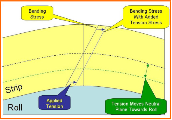
When strip bends over a roll without applied tension, a neutral plane exists approximately at the centre thickness. Strip outside this plane is in tension; inside it is in compression. All the plastic work occurs at the point where strip first conforms to the roll; increasing wrap angle beyond this point adds no further effect. Once intermesh is sufficient to fully conform the strip to the roll, further increases in intermesh have no additional benefit.
Applying tension moves the neutral plane toward the roll surface, increasing tensile deformation of the free surface and decreasing compression of the inner surface. As strip passes over successive opposing rolls, it progressively elongates. The levelling action removes shape defects because reduced tension in longer fibres causes them to elongate proportionally less than shorter (tighter) fibres – thereby equalising fibre lengths across the width.
4. Temper Rolling: Equipment and Process Overview
Temper mills superficially resemble cold rolling stands but differ significantly in operating parameters. Temper rolling loads are typically a few hundred tonnes; cold rolling loads are several thousand. Galvanising line speeds are lower than cold rolling or batch-annealing temper rolling speeds. As a result, motor/drive systems and backup roll bearing requirements are substantially reduced, and the high-modulus housing required for gauge control in cold rolling is unnecessary.
Mill Configuration
Modern galvanising line temper mills use a 4-high design. Hydraulic screws allow operation in load-control mode – useful when lifting rolls for welds and line stops. Work roll diameter affects bending response, roll life and roughness transfer. Some mills maintain two work roll diameters: smaller diameters for harder grades, larger for soft interstitial-free (IF) grades where rolling loads can be as low as 50 tonnes – approaching the weight of the upper roll stack itself – requiring a special mode that lifts the top backup with roll balance cylinders.
Hydraulic work roll bending (crown-in and crown-out cylinders acting between roll chocks) enables roll-gap profile adjustment without changing rolling load – the primary shape control mechanism. A small chamfer on backup roll ends significantly increases crown-in bending effectiveness, especially on wide strip.
Entry and Exit Intermesh Rolls
Entry and exit intermesh rolls (also called anti-crimp and anti-cross-bow / billy rolls respectively) control the angle at which strip approaches and leaves the roll bite. The entry roll stabilises manifest shape defects by "piling up" excess length before the bite. Both rolls cause strip to contact the top work roll slightly outside the bite, stabilising entry and exit.
Strip deformation around these rolls creates a through-thickness stress field that influences cross bow – the exit roll partially corrects any cross bow induced by the mill. Entry and exit rolls are separately adjustable and are typically mounted at approximately 45° to the horizontal, close to the work roll; they must be retracted during roll changes.
Work Roll Cleaning and Changing
On-line roll cleaning substantially increases work roll life by removing metallic debris and dirt that accumulates during dry temper rolling. Cleaning is typically by traversing mildly abrasive media (such as a Scotch-Brite-type material stored as a long roll for automatic replacement) or by brushes acting on the exit surfaces of both work rolls.
Rapid roll changes are facilitated by track-mounted cars and hydraulic push systems, and by driving only the backup rolls – eliminating the need to engage spade couplings on work roll ends. Wet temper fluid (water-based, detergent-containing) is delivered by low-volume sprays upstream of the roll bite, with flow manually controlled based on visual observation of the puddle ahead of the bite.
Rolling Theory in Temper Mills
Temper rolling involves conditions quite unlike hot or cold rolling, where reductions are typically 10–100 times greater. Conventional theories for roll separating force fail under temper rolling conditions – they require unrealistically high friction coefficients to fit measured data. The discrepancy is believed to arise from the non-circular roll contact arc and from asymmetric deformation due to non-zero entry and exit angles. Elastic compression and recovery zones can be large compared to the plastic deformation region, adding significantly to rolling force without creating permanent deformation. Rolling processes in temper mills remain poorly understood and predictive capability is limited compared to other rolling conditions.
5. Strip Shape Control by Temper Rolling
In cold rolling under plane-strain conditions, any change in percent crown is directly associated with a corresponding shape change. Strip with 500 I units of edge wave – meaning the edges are 0.5% longer than the centre – would be corrected by a rolling pass that decreases percent strip crown by 0.5%, extending the centre to match the edges. In the temper mill, the required profile changes are extremely small (hundredths of 1%), effectively undetectable with a standard micrometer.
Shape control engineers decompose measured shape into components addressed by different actuators. A typical shape measurement may simultaneously contain:
- An asymmetric deviation (camber) – corrected by mill level adjustment
- A symmetric deviation (edge wave or centre buckle) – corrected by roll bender settings
A ground work roll crown is selected to position the loaded roll-gap profile in the correct range; typically this is just a few thousandths of an inch and difficult to measure reliably. Shape control actuators include:
- Roll bending (crown in/out) – primary actuator for symmetric shape
- Mill level control – for camber
- Pair crossing (PC) – increases roll-to-roll distance at strip edges without affecting the centre; used at some facilities as a deliberate shape control mechanism
- Work roll side shift
- Inflatable (Nipco) backup rolls – increase crown with internal pressure
Roll bending effectiveness increases substantially with strip width. Actuator gain settings must be adjusted accordingly. Automated shape control systems, now standard in cold rolling mills, remain largely absent in galvanising line temper mills – operators adjust bender settings manually, typically from a downstream viewing position where tension is low enough to reveal the true flatness of the strip.
6. Elimination of Discontinuous Elongation
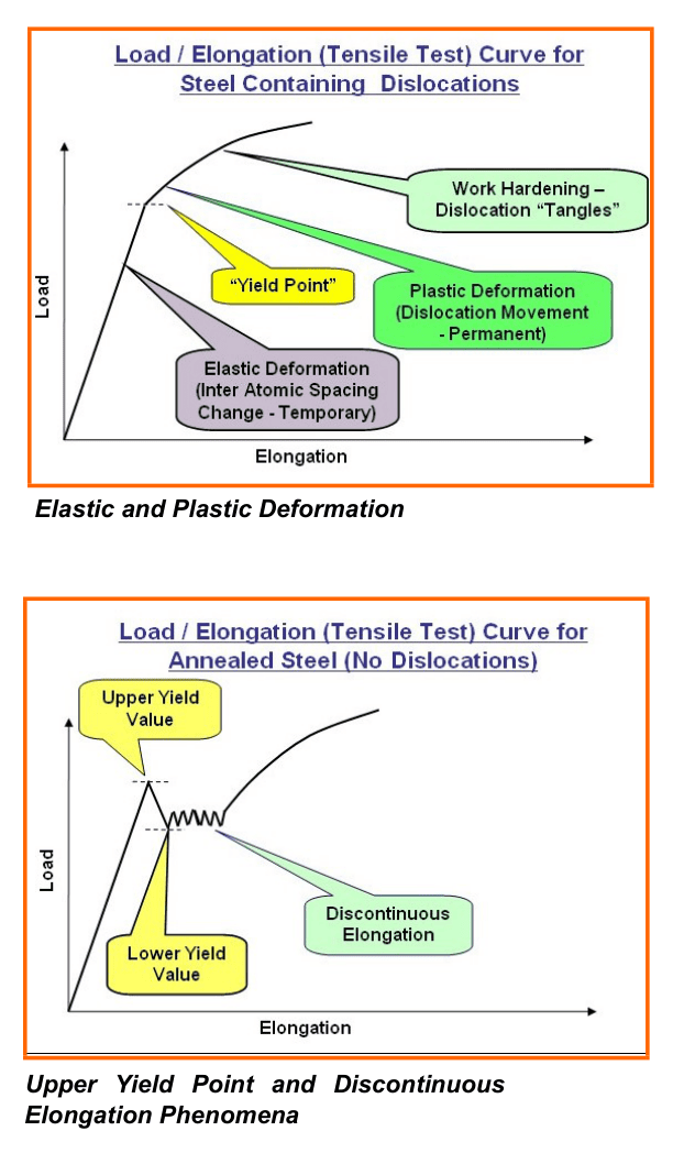
When metal crystals are loaded, inter-atomic spacing changes elastically (Young's modulus, approximately 210 GPa for steel) up to the yield point. Beyond this, pre-existing dislocations move along slip planes, creating permanent plastic deformation. A problematic condition occurs in annealed steels from which dislocations have been eliminated and/or pinned by interstitial carbon and nitrogen (forming "Cottrell atmospheres"). This is typical of the low-carbon, non-IF grades that constitute a large proportion of galvanising line production.
In the absence of mobile dislocations, the stress required to initiate plastic deformation rises to an upper yield point – the level needed to generate new dislocations. Once generated, these dislocations traverse at the lower yield stress, causing localised deformation before work hardening restores resistance. This produces discontinuous elongation: a ratcheting pattern in the load-extension curve as dislocations alternately nucleate at higher stress and traverse at lower stress. The contrast between normal and annealed steel behaviour is illustrated below.
The consequences are:
- Lüders bands – surface lines transverse to the deformation direction caused by localised strain concentration. Tension levelling produces many fine bands visible at low magnification, unacceptable for most painted surfaces. Temper rolling produces analogous deformed regions that propagate at approximately 45° through the strip thickness but are not associated with visible surface markings.
- Fluting – during bending, continued deformation at the initial yield location causes strip to fold in discrete creases separated by undeformed flats, making smooth forming practically impossible.
- The upper yield phenomenon is a factor that limits success in computer modelling of temper rolling. Asperity peaks on rough rolls may cause local yielding at pressures well below the bulk upper yield stress, reducing effective yield from the upper to lower value – possibly explaining the observed anomaly whereby rougher rolls promote greater reductions for a given roll force, contrary to normal rolling theory.
Discontinuous elongation is eliminated by introducing dislocations and dislocation sources into the steel through plastic deformation. A minimum elongation of approximately 0.5% is required. Both temper rolling and roll-intermesh tension levelling achieve this adequately; the choice between them normally depends on surface requirements for the product.
After temper rolling, interstitial carbon and nitrogen can re-diffuse and pin the new dislocations, partially restoring discontinuous behaviour – a process known as strain ageing or age hardening. This is time- and temperature-dependent, which is one reason strip is cooled to below approximately 40°C in the quench tank before entering the temper mill. Extended storage in warm conditions after temper rolling may allow some return of yield point behaviour. Interstitial-free (IF) steel grades eliminate this risk by reducing carbon and nitrogen to the lowest practicable levels and tying up residual amounts in stable compounds with titanium or niobium.
7. Surface Conditioning by Temper Rolling
Temper rolling of uncoated (batch or continuously annealed) strip is well-established technology, with several work roll surface texturing processes available: shot blast texturing (SBT), electric discharge texturing (EDT), electron beam texturing (EBT) and laser texturing. SBT and EDT produce random surfaces; EBT and laser texturing create deterministic (geometrically defined) finishes. In terms of roll wear resistance and surface stability, EBT and SBT texturing processes have been reported to produce the longest-wearing roll surfaces.
For uncoated steel, the specified surface roughness (Ra in microinches, peaks per inch) – typically 25–50 µin Ra with 125–250 peaks/inch – is primarily required for lubricant entrapment in press-forming operations. A maximum roughness limit prevents asperities from degrading paint appearance.
Temper Rolling of Zinc-Coated (GI) Strip
Pure zinc is soft and consists of hexagonally close-packed crystals, a structure with limited slip planes and therefore prone to cracking in some crystal orientations. The as-galvanised surface of spangle-containing coatings has significant long-range topography associated with spangle crystal boundaries. Temper rolling must reduce this surface morphology to a level that will not degrade paint appearance. Temper rolling also:
- Disrupts alumina-rich surface oxide layers, improving paint adhesion through increased effective surface area and chemical activity, and providing some mechanical keying of the first paint layer
- May reduce friction in press-forming of unpainted strip by creating lubricant-retention reservoirs
- Crushes small protruding surface defects, improving paint appearance and significantly reducing coil build-up defects during rewinding – some facilities temper roll heavy-gauge coils purely for the yield improvement this delivers
Roughness transfer from work rolls to zinc-coated strip depends on rolling force, wet or dry operation and the roll texturing process. At low pressures, roll asperities penetrate into the zinc coating. As pressure increases, the mechanism shifts to reverse extrusion: zinc flows into inter-asperity spaces. Texture transfer increases approximately linearly with elongation up to about 1.0%, after which a saturation condition develops as inter-asperity spaces approach full occupancy. Wet temper rolling reduces texture transfer because temper fluid trapped in surface features is compressed rather than displaced.
Temper Rolling of Galvanneal (GA) Strip
Galvannealed (GA) coatings are substantially harder than zinc GI – consisting of zinc-iron alloy crystals (predominantly zeta phase at the surface in conventional processing, or delta phase in longer/higher-temperature galvannealing cycles, which is harder still). The surface contains both short-wavelength components (from zinc-iron phase morphology) and long-wavelength components inherited from the substrate. Temper rolling reduces both, with the reduction in long-wavelength components being the more substantial. Data reported by Sakurai, Inagaki and Yamashita[1] shows a marked reduction in friction coefficient as temper rolling elongation increases from 0 to 1.5%.
References
- Sakurai, M., Inagaki, J. and Yamashita, T. (1995) 'Effects of Surface Texture of Galvannealed Steel Sheet on Image Clarity After Painting', Galvatech '95, Iron and Steel Institute of Japan.
- Kapellner, A. (1995) 'New Developments in Skin Passing for Hot Dip Galvanising Lines', Galvatech '95.
- Cervellini, G. and Migliornio, D. (2004) 'Siderar's Experience with Wet Skin Passing', Galvanisers Association Meeting 2004.
- Norden, M. and Hesling, S. (2013) 'Strip Roughness Control in Galvanising Line Temper Mills', Galvanisers Association Meeting 2013.
Next Steps for Your Business
Optimising temper rolling and tension levelling can deliver significant benefits in your galvanising line, including:
- Improved strip flatness and shape consistency
- Elimination of Lüders bands and surface defects
- Better coating adhesion and paintability
- Reduced customer complaints and rejects
If you are looking to improve strip quality or reviewing your temper mill equipment specification, why not give us a no-obligation call? Our experts will be pleased to discuss your requirements with a view to an initial concept study.
152 projects in 48 countries since 2001
Free, confidential first conversation No obligation Reply within one working day

| Air Knife & Coating Mass Control | Air knife design, X-ray coating measurement, edge baffle systems and automated coating mass control in galvanising lines. |
| Coil Winding in Galvanising Lines | Radial and tangential stress in wound coils, strip compressibility, telescoping and other winding failure modes and corrective actions. |
| Dross Formation & Control | Dross composition and formation mechanisms, economic cost of coating metal loss, removal practice and aluminium bath control. |
| Plate Mill Yield and Provisioning | Provided yield and provisioning, yield cost and margin loss, plan view rolling, scale loss and hydraulic gauge control in plate mills. |
| Strip Centring in Vertical Furnaces | Roll crown mechanics, the balance between tracking-off and heat buckle, ground crown profiles, roughness and thermal crown control in vertical furnaces. |
| Side Trimming in Steel Pickle Lines | Side trimmer knife gap setup and resulting cut edge characteristics, defects from incorrect knife gap, hold-down pressure and how poor trimming causes serrated edge. |
How to Cite This Article
Hesling, S.W. (2026) 'Temper Rolling and Tension Levelling in Galvanising Lines', SteelOnTheNet Technical Reference Series. Available at: https://www.steelonthenet.com/resources/technical/temper-rolling-tension-levelling.html (Accessed: 26 October 2026).