Coating Mass Control
Published:
This technical module covers the principles and practice of air knife technology and zinc coating mass control as applied in continuous hot-dip galvanising lines. It forms part of a series of galvanising line technical reference modules authored by Steven W Hesling.
1. Introduction
Strip vertically exiting a galvanising bath carries with it a quantity of liquid coating metal. The actual quantity is a function of line speed, and the density and viscosity of the liquid metal, and the roughness of the strip surface. In almost all cases this quantity of metal is far in excess of the required coating mass, and must be reduced to a controlled level.
Early systems used wipes and rollers to mechanically remove excess coating. These were superseded by the development of gas jet coating knives – devices which direct a high-velocity gas stream at the strip surface to wipe excess metal back towards the bath.
Gas jet knives consist of a plenum chamber from which gas flows through a carefully designed slot between two long parallel lips spanning the full width of the strip. A typical lip-to-lip gap is in the order of 1.2 mm (0.050 inches). Both knife-to-strip distance and wiping gas pressure are adjusted to control coating mass.
Steam was initially a popular wiping medium in galvanising lines but was replaced by air by the 1970s. More recently, nitrogen wiping has been adopted for surface-critical automotive exposed products, where it produces a brighter surface appearance, though the mechanism remains uncertain. Nitrogen adds significant cost and is unlikely to find wide application beyond critical products.
2. Measurement of Coating Mass
Weigh–Strip–Weigh Testing
The traditional method for measuring coating mass was weigh–strip–weigh testing. Samples were cut and weighed, the zinc removed with inhibited hydrochloric acid, then the samples were washed, dried and re-weighed. Coating mass was calculated from the sample area and weight loss. The test is slow, requires precautions for working with strong acids and performs poorly in reproducibility and repeatability (R&R) evaluations. It also provides data from only one small location at the end of a coil.
X-Ray Fluorescence Gauges
X-Ray Fluorescence (XRF) coating mass gauges have now replaced weigh–strip–weigh testing as the standard production tool. They project an X-ray beam with sufficient energy to penetrate through the coating layer and into the steel substrate. The beam excites k-shell electrons, which fluoresce at characteristic energies as they return to their ground state: Zn = 8.6 keV, Fe = 6.4 keV. The quantity of zinc present is estimated from the intensity of fluorescence radiation reaching a detector.
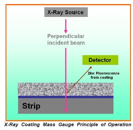
XRF gauges are proven and effective for zinc (GI) coating mass. Measurement of zinc and iron in galvanneal (GA) coatings is more complex and may involve multiple incident beams at different angles, with determination based upon the differential between measurements. Gauges require regular calibration using galvanised strip standards, which are themselves characterised by careful weigh–strip–weigh determinations and, where necessary, ICP analysis of the resulting solution. Sophisticated testing strategies are used to create these calibration standards, designed to provide both the best possible estimate of actual coating mass and a confidence level for each standard.
Gauge Configuration and Traverse
XRF gauges typically have two traversing heads – one for the top surface and one for the bottom – which scan back and forth across the strip width while the strip moves underneath, producing a zig-zag measurement pattern. One edge-to-edge traverse takes approximately 15 seconds, during which around 30 metres of strip pass through the machine.
Galvanised strip contains coating mass variation in both the transverse and longitudinal directions, and top and bottom surface masses often differ substantially – frequently with an inverse correlation. Raw data from a single traverse contains the combined effects of both types of variation, making it impossible to separate them without further processing. This is a significant challenge for automated control systems, which must determine the nature of any deviation before applying corrections.
Gauge Location
Gauges have traditionally been placed at floor level, below the process tower, where they provide a good environment for equipment and easy access for calibration. However, this creates a very long feedback loop – one of the main obstacles to effective automated coating mass control. Water remaining on the strip from a quench tank above can also cause serious measurement errors at this location.
A gauge at the top of the process tower provides a shorter feedback loop and a reasonable equipment environment. “Hot” gauges positioned directly above the pot offer the shortest possible feedback loop but face challenges with strip position stability and traversing mechanism reliability in that environment. In some installations – such as at thyssenkrupp – a fixed (non-traversing) hot gauge on the strip centreline feeds a fast inner control loop, complementing a conventional traversing gauge further downstream.
3. Coating Mass Specifications and Standards
ASTM Average Coating Weight Specifications
Traditionally, most zinc-coated steel in North America was manufactured and sold to ASTM designations such as G40, G60, G90 or G120. The numbers represent the nominal combined two-side minimum average coating mass in imperial units – for example, G90 requires an average of 0.9 oz/ft² of zinc, equivalent to 276 g/m². There is no maximum coating weight in this specification.
ASTM also provides equivalent metric unit designations using the prefix Z followed by the nominal coating mass in g/m². For Z275, for example:
- Minimum two-side coating mass at any single spot: 235 g/m²
- Minimum average of three single-spot tests: 275 g/m²
- Minimum average of all three measurements on one side: 94 g/m²
This specification contains a notable loophole: an area on one side could theoretically be completely uncoated, provided other areas compensate the average. (The coil would, however, presumably fail the uncoated spot defect requirement.) It also permits an aggressive coating weight aim value at coil start, since a modest initial underweight is very unlikely to cause rejection and can be compensated later in the coil.
Underwriters Laboratory (UL) Certification
Many customers in North America require UL certification of coating weight. UL is not itself a specification but an organisation that defines, audits and approves the coating weight measurement procedures carried out by manufacturers. For Z275, UL requires that each single-spot, single-side measurement be a minimum of 94 g/m² – in effect closing the loophole in the base ASTM standard.
Single-Spot Minimum (“Automotive”) Specifications
A strong case can be made that it is the lowest coating value at any point – not the average – that determines product service life. Single-spot minimum specifications, sometimes called “Automotive” specifications because they were initially required by car companies, are based on this principle. They include both a minimum and a maximum coating mass at every location within the coil.
ASTM now provides a standard of this type (see Appendix). For example, 50G requires a minimum of 50 g/m² and a maximum of 100 g/m² at every single spot. Upper limits reflect concerns about the adverse effect of excessive coating mass on spot welding electrode life, among other issues. Automotive producers all apply this concept, but their specific minimum and maximum values vary significantly.
It is increasingly common for customers to require process data, including coating mass scan data. This raises issues – such as transition lengths, how transition material is distributed across a weld and sample spot size – that are not adequately addressed by specifications developed before the widespread use of X-ray gauges.
4. Target Optimisation and Zinc Cost Saving
Over-coating of galvanised strip has been reported as averaging around 15% of total coating metal consumption.[17] Even a modest improvement in this figure will typically pay for a state-of-the-art automatic coating mass control system in less than one year. For example, a line producing 200,000 t/yr of average 0.024-inch strip can save approximately US$550,000 annually by reducing over-coating on nominal G60 product from an average of G66 to G63 (based on 2017 LME zinc prices).
The key mechanism is illustrated by the classic “bell curve” diagram: automatic control narrows the distribution of coating mass values, allowing the aim point to be set closer to the specification minimum – achieving zinc cost savings without increasing the statistical risk of producing below-minimum product.
In steady-state conditions, a standard deviation calculation can determine the aim value corresponding to an acceptably low incidence of under-mass coating. In practice, however, process disturbances vary considerably in scale and character. The most severe is a product change involving both a strip thickness change (requiring a line speed change) and a major alteration in aim coating mass – conditions that can simultaneously alter strip cross bow in the knives and fundamentally change the transverse coating mass profile. Simply including such transition data in a standard deviation calculation produces an unrealistically high target value.
In an ideal world, the target value would be continuously optimised, accounting for both current conditions and anticipated changes. Bob Wilhelm[14] has described the general target selection problem as a linear programming exercise with constraints on average bottom coat weight, average top coat weight, average total coat weight, top-to-bottom ratio, and hard upper and lower limits on the target.
5. Air Knife Technology
Knife Design and Gas Flow
An air knife consists of an elongated plenum chamber extending across the full width of the strip, preferably supplied with gas from both ends to improve transverse pressure uniformity. From the plenum, wiping gas flows at high velocity through a slot between two carefully machined knife lips. The gas stream impinges against the strip surface, creating both a pressure distribution and a shearing action that together wipe excess liquid coating back towards the bath.
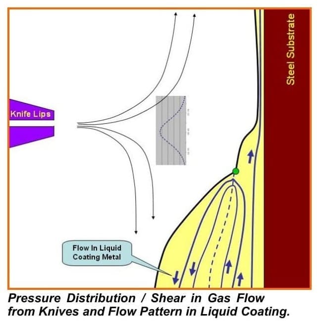
Gas leaves the plenum through a series of circular holes in intermediate baffles designed to produce calibrated pressure drops and improve transverse uniformity. Wiping gas reaches high velocities as it passes through the knife slot; at high knife pressures, flows can approach sonic velocities. Danieli Kohler[18] report that the optimal use of high-subsonic knives requires a maximum pressure of approximately 800–850 mbar (11.3–12.0 psi) at the knife; above this limit, a differently designed nozzle is needed to ensure stable jet expansion.
The external profile of the knife lips and body is designed to provide good access for the atmospheric air that entrains with the jet flow. Such entrainment air is especially important on the strip-entry side of the jet impingement plane; both Kohler and Fontaine knives therefore incorporate an offset of the lip slot relative to the plenum, locating almost the entire knife body above the impingement point.
Wiping Mechanics
The knife jet creates a stagnation pressure distribution at the strip surface, together with shear stress as gas deviates away from its initial path. Liquid flows within the coating metal are complex: below the impingement zone, a counter-flow exists – metal close to the strip moves upward while metal at the free surface moves downward. The net upward flow equals the final coating mass on the strip. The neutral plane (where there is no net zinc flow) and the reversal point (where surface flow changes from downward to upward) are both key features of the wiping process.
Maximum wiping action is obtained when both the pressure at the strip surface and the shear stress peak simultaneously. Research by Danieli Kohler[18] shows that, over a wide range of pressures, both are maximised with knife lip gaps in the range of 0.8–1.0 mm; increases or decreases outside this range reduce wiping effect.
Knife Angle and Splashing
Knife angle relative to the strip can be varied slightly. A downward inclination (typically about 5°) is widely believed to reduce the incidence of knife plugs (caused by zinc spitting onto the lip surface and freezing there) and is well-established as reducing splashing. Upward angles increase the risk of splashing.
Splashing occurs when making light coatings at high line speeds and is associated with instability of the liquid surface in the vicinity of the air knives, eventually leading to the separation of zinc droplets. It typically initiates at the strip edges before propagating across the full width. Splashing greatly increases dross generation rates and adversely affects coating weight control. When encountered, line speed must be reduced – and to reverse an established splashing condition, it may be necessary to reduce speed well below the onset velocity.
6. Air Knife Setup
Knife Rig Mounting and Gas Supply
The gas delivery system to the air knives is complex. It typically starts with hoses from two separate blowers, joining into a single line before dividing to the two knives. Pressure-regulating valves in each knife line allow independent pressure control. The flow passes through several right-angle turns before entering the knife plenum; at the high flow rates involved, pressure losses at bends and discontinuities can be significant, and supply piping design should minimise these through smooth turns and transitions.
Knives are mounted on two parallel beams spanning across the bath, with a third central beam carrying the edge baffles. Both knives and baffles must be able to adjust height above the bath; the horizontal position of each end of each knife should ideally be independently adjustable, enabling correction of skew and wedge coating profiles. Knife rotation is accomplished via actuators at the knife-to-beam connection; position transducers for both horizontal position and rotation require a reliable supply of cooling air in this hostile environment.
Knife Setup and Zeroing
Knives are normally removed during each change of pot equipment and thoroughly inspected and calibrated. Knife lip parallel – ensuring that neither front lip edge protrudes forward of the other – is one of the most critical setup parameters, as it determines both the jet angle and flow quality. It is checked using a precision square referenced from the machined bottom face of the lower lip.
Lip slot gap is measured using feeler gauges. A “bowtie” profile – wider gap near the strip edges than at the centre – is commonly used to create a coating mass profile that reduces the risk of edge buildup defects during coiling. Knife lips should never be cleaned with sandpaper or other harsh abrasives, particularly in the critical internal flow region.
Zeroing knife angles uses a digital protractor referenced from the machined bottom face of the lower knife (negative angle = flow directed downward toward the bath; positive = upward). Knife-to-knife distance and parallel are established by gently lowering a calibrated soft metal (preferably aluminium) wedge between the knives, repeated at each end.
Knife Plugs
Knives are prone to develop plugs in the near-edge region, caused by small molten zinc particles spitting onto the knife lip surface and freezing there. The result is a line of increased coating weight and coil buildup. Traditional cleaning involves opening the knives and passing a feeler gauge cleaner along the slot – a slow process producing a significant length of defective strip. Some knife designs incorporate fast internal traverse cleaners, which substantially reduce product loss, though reliability and ability to clean the front lip edge can be problematic.
7. Sources of Coating Mass Deviation
Changes in coating weight target and line speed are frequent disturbances that can be corrected almost instantaneously by a coating weight control system. A number of other issues routinely occur that cannot readily be corrected by automated systems and remain under operator control:
- Strip displacement from the centreplane between the knives. This causes one side to increase in coating mass while the other decreases by approximately the same amount. It typically occurs when a change in tension, product thickness or mechanical properties alters the curvature of the strip as it leaves the upper stabiliser roll. Speed changes can also cause a similar effect on thin, high-speed product.
- Strip cross bow (“canoe”). This transverse curvature causes a similar but edge-confined high/low coating deviation between the two surfaces. It occurs when one surface is stretched more than the other as strip passes around the pot stabiliser rolls. Factors affecting it include tension, mechanical properties and strip thickness.
- Strip vibration. Vibration between the knives causes substantial cyclic coating mass changes, typically at a frequency of around 1 Hz. This is discussed further in Section 10.
- Changes in strip roughness. Most commonly occurring at a weld; increased roughness increases coating weight.
- Water on the strip. Water remaining from a quench tank above a floor-level gauge causes significant measurement errors, prompting the control system to correct for an error that does not exist and thereby introducing an opposite error.
8. Edge Baffles and Edge Buildup Control
Edge baffles are typically heavy steel plates (up to 3 mm thick) positioned against the edges of the strip in the knife region. They are designed to eliminate the strip edge discontinuity and the vortex and turbulence that this tends to cause. Such turbulence increases coating in the near-edge region, potentially leading to edge buildup defects in the coil, as well as pickup of oxides and dross. Baffles also substantially reduce noise, particularly when high pressures create near-sonic velocities.
Edge buildup problems are most pronounced when making heavy coating weights, because the low pressures and large knife-to-strip distances required are especially prone to turbulence. Galvalume and aluminise coatings are also particularly susceptible for similar reasons.
To function effectively, baffles must be positioned in the same plane as the strip, with their edges almost but not quite touching the strip edges. Maintaining this positioning is demanding: adverse conditions above the pot affect equipment reliability, and strip position varies with vibration, cross bow and other shape deviations. In practice, all baffle designs remain demanding of operator attention; no design can be said to be entirely satisfactory.
The preferred baffle design for Galvalume is a “beaver tail” – a thin strip of metal attached perpendicularly to the edge of the baffle plate, adjacent to the strip. This significantly reduces the consequences of moderate out-of-plane strip deviations. A quick-change system allows different width beaver tails to be swapped as required, maintaining a knife-to-knife distance minus beaver tail dimension of 5–10 mm.
Baffles are susceptible to zinc pickup below the knives. Various materials and coatings have been tried in pursuit of anti-stick behaviour, with varying success. Poorly positioned baffles can be worse than no baffles at all.
9. Coating Weight Models and Automated Coating Mass Control
The Control Problem
Coating weight control is unusually complex. Coating mass varies in both transverse and longitudinal directions and between the two surfaces. Multiple actuators address some but not all disturbances. Line speed is the only incoming condition that can be reliably measured and adjusted for. The coating measurement gauge is typically located far from the pot, creating a long time constant that complicates the control process. Establishing an optimal target is itself non-trivial, as discussed in Section 4.
Historically, coating mass control systems automated knife pressure and horizontal knife position to address longitudinal variation – applying feedback control for mean coating and skew, together with feed-forward control for mean coating based on line speed. Other adjustments (stabiliser roll intermesh, knife height) remain under operator control.
Actuator Selection
Both knife pressure and knife-to-strip distance (horizontal knife position) are effective actuators. Coating mass varies approximately linearly with knife-to-strip distance but non-linearly with knife pressure, making distance the theoretically preferable choice for large corrections. Only position control can correct skew and wedge errors. However, horizontal knife movement carries a risk of catastrophic strip-to-knife contact, and position drives and transducers are less robust under the high number of movements required for continuous coating control. Pressure control valves are more durable. A composite approach is therefore generally preferred:
- Knife position to correct skew and wedge errors, and for large setup changes
- Knife pressure for ongoing small adjustments
In the absence of a reliable direct knife-to-strip measurement device, the coating mass model is inverted to estimate knife-to-strip distance from measured coating mass, pressure and line speed. This “soft sensor” approach is adequate but less than ideal. Reliable non-contact measurement of strip position remains an unsolved industry challenge.
Coating Weight Model
An accurate process model is essential in coating mass control due to the long time constant created by the remote gauge position. Early systems used statistical regressions of recorded operator practice; modern systems are based on fast and efficient numerical solution of the Navier–Stokes equations to predict the coating mass resulting from an applied pressure and shear stress distribution.
Thornton and Graff[4] provided an early model in which gravity is augmented by the gas pressure gradient created by the jet. Ellen & Tu and subsequent authors[2][3][5] improved this by also accounting for the shear stress created at the liquid coating surface by the wiping jet, significantly improving agreement with industrial data.
A remaining challenge is accuracy at small knife-to-strip distances – specifically where the ratio of knife-to-strip distance (Z) to knife slot opening (d) is less than 8. At such distances, the potential core of the jet reaches the strip surface, producing a “flat-topped” pressure distribution rather than the Gaussian profile measured at greater distances. More recent work[19][20] has demonstrated significant accuracy improvements by using a flat-top pressure distribution as a boundary condition when Z/d < 8, though this requires transitioning between model types at the discontinuity.
IAS has reported that their Navier–Stokes based model predicts coating mass of transition coils with a standard deviation of 5% across a full range of normal operating conditions.
The Dynamic Air Knife (DAK)
The only commercial technology with the potential to actively correct local and symmetric transverse coating mass deviations is the Dynamic Air Knife (DAK), developed by Clecim in the early 1990s. The DAK uses 20 mechanical actuators (10 per lip) to dynamically adjust the knife slot profile across the strip width, in addition to conventional actuators for corner position, pressure and height. Results from an installation at IMSA in Mexico, re-automated by IAS in 2004, have generally been reported positively,[13] but whether the benefits of variable slot geometry currently justify the additional cost and complexity remains unclear.
10. Strip Stability Within the Coating Knives
Strip is prone to vibrate in the long unsupported span between the last pot stabiliser roll and the first tower roll. This occurs at frequencies between approximately 1 and 10 Hz, creating cyclic strip displacement within the coating control knives. The consequences are large cyclical coating mass variations, potential destabilisation of the coating process (promoting splashing) and a requirement to increase knife-to-strip distance to avoid strip-to-lip contacts – the opposite of what is desired when making light coatings at high speed.
Strip vibration is therefore an area of considerable current interest and development. The strip can exhibit simple string vibration, torsional vibration and flutter (a cyclically reversing cross bow condition where strip edges move in a “flapping wings” motion). Research by Dubois and Gaignard & Dubois[21][22] identifies two main excitation sources:
- Pot roll rotation (roll deformation, eccentricity, etc.)
- Powerful forced air strip cooling in the process tower (vibration amplitude increases with cooling power)
Increasing strip tension generally reduces vibration amplitude while raising frequency. Hot bridles, installed in place of furnace turn-down rolls, can provide higher strip tensions without risk of necking in the hot zone. However, higher tension can also raise the natural frequency of the system into resonance with a pot roll or other excitation source, so results may not always be as intended.
Stable Cooling Gas Delivery
Conventional strip cooling devices (holes, nozzles or slots directing cooling air) can generate turbulent and uneven gas flows that excite strip vibration. Spooner Industries developed an air-floatation cooling system[23] using staggered, slightly intermeshing pressure pads through which thin strip passes in a sinusoidal wave form. This system is claimed not to cause vibrations and to have a positive damping effect on vibration from other sources – with damping improving as nozzle velocity increases, due to the increased clamping force. CMI promotes a similar technology called Blow-Stab.
Electromagnetic Strip Stabilisation
The other major approach uses electromagnets that can be rapidly actuated to damp strip movement based on position sensor signals. The magnets do not clamp the strip but apply a corrective force at an appropriate point in the vibration cycle. EMG has installed such systems at thyssenkrupp in Germany and at facilities in North America, employing five opposing pairs of electromagnetic clamps located across the strip width.
Reported data[24] shows standard deviation of coating mass being reduced by 50% or more when the system is activated. The greatest practical benefit appears to be in extending operating cycles between pot equipment changes, when roll eccentricity and bearing wear are the main vibration drivers.
References
- Tamura, T., Kitayama, M. and Kitazawa, Y. (1985) 'Splashing Control in Continuous Hot Dip Galvanising', First International Conference on Zinc Coated Sheet, Munich.
- Ellen, C.H. and Tu, C.V. (1982) 'An Analysis of Jet Stripping of Molten Metallic Coatings', Eighth Australasian Fluid Mechanics Conference.
- Tu, C.V. (1996) 'On the Limits of Withdrawal Speed in the Gas Wiping Process', Australian Engineering.
- Thornton, J. and Graff, H.F. (1976) 'An Analytical Description of the Jet Finishing Process for Hot Dip Metallic Coatings on Strip', Metallurgical Transactions, December.
- Tu, C.V. (1990) 'Optimisation of Lip Gap for Thin Film Coating in the Jet Stripping Process', Institution of Engineers Australia Conference, Wollongong.
- Edwards, W.J., Carlton, A.J. et al. (1976) 'Coating Mass Control System Design for a Continuous Galvanising Line', Automatica, Vol. 12, pp. 225–235, Pergamon Press.
- Wilhelm, R. (2001) 'Evaluating Air Knife Adjustments with the Aid of a Coating Weight Model', Galvanizers Association Meeting.
- Goodwin, G., Lee, S.J., Carlton, A. and Wallace, G. 'Application of Kalman Filtering to Zinc Coating Mass Estimation'.
- Davene, J. et al. (1995) 'Dynamic Air Knives', Galvatech '95.
- Adams, J. et al. (1996) 'Coating Mass Control on No. 2 Galvanising Line at LTV Steel's Indiana Harbor Works', Iron and Steel Engineer, January.
- Dubois, M., Buchlin, J.M. et al. (2004) 'Effect of Nozzle Tilt Upon Splashing in Jet Wiping', Galvatech 2004.
- Gaignard, S. and Dubois, M. (2004) 'Characterisation of Vibration at the Wiping Nozzles', Galvatech 2004.
- Hochstetter, K.M. et al. (2006) 'Variable Geometry Air Knife Control Utilising Constrained Model Predictive Control', Galvanizers Association Meeting.
- Wilhelm, B. (2006) 'What Does it Mean to Control Coating Weight?', Galvanizers Association Meeting.
- Wilhelm, R.G. (1972) 'Controlling Coating Weight on a Continuous Galvanising Line', Control Engineering, Vol. 19.
- Deka, M. (1995) 'Procedure for Generating Calibration Standards for Galvanised and Galvaneal Product', Galvanizers Association Meeting.
- Wallace, G. and Voss, G. (2005) 'Metal Coating Control Economics', Galvanizers Association Meeting.
- Vecchiet, F., Zorut, M. et al. (2006) 'Development of Air Knives Using Fluid Dynamics Modelling', Galvanizers Association Meeting.
- Elsaadawy, E.A. et al. (2007) 'Coating Weight Model for the Continuous Hot Dip Galvanising Process', Metallurgical and Materials Transactions.
- Elsaadawy, E.A. et al. (2003) 'Air Knife Coating Weight Models — Improvements at Near Knife to Strip Distances', Galvanizers Association Meeting.
- Dubois, M. (2005) 'Strip Vibration Back to Basics', Galvanizers Association Meeting.
- Gaignard, S. and Dubois, M. (2004) 'Characterisation of Strip Vibration at the Wiping Nozzles', Galvatech 2004.
- Henderson, P. et al. (2002) 'Air Floatation Technology for Post Pot Cooling and Strip Stabilisation', Galvanizers Association Meeting.
- Irle, M. et al. (2007) 'EMG-eMASS Increasing Throughput and Reducing Zinc Consumption in HDG Lines', Galvanizers Association Meeting.
Next Steps for Your Business
Optimising air knife setup and coating mass control can deliver significant operational and commercial benefits in your galvanising line, including:
- Reduced zinc consumption through tighter coating weight distribution
- Fewer coating defects and customer rejections
- Shorter transition lengths at product changes
- Improved compliance with single-spot minimum automotive specifications
If you are looking to improve coating mass control performance or reviewing your air knife and automation equipment specification, why not give us a no-obligation call? Our experts will be pleased to discuss your requirements with a view to an initial concept study.
152 projects in 48 countries since 2001
Free, confidential first conversation No obligation Reply within one working day

| Temper Rolling & Tension Levelling | Strip shape principles, tension levelling and temper rolling equipment, discontinuous elongation and surface conditioning of zinc-coated strip. |
| Coil Winding in Galvanising Lines | Radial and tangential stress in wound coils, strip compressibility, telescoping and other winding failure modes and corrective actions. |
| Dross Formation & Control | Dross composition and formation mechanisms, economic cost of coating metal loss, removal practice and aluminium bath control. |
| Plate Mill Yield and Provisioning | Provided yield and provisioning, yield cost and margin loss, plan view rolling, scale loss and hydraulic gauge control in plate mills. |
| Strip Centring in Vertical Furnaces | Roll crown mechanics, the balance between tracking-off and heat buckle, ground crown profiles, roughness and thermal crown control in vertical furnaces. |
| Side Trimming in Steel Pickle Lines | Side trimmer knife gap setup and resulting cut edge characteristics, defects from incorrect knife gap, hold-down pressure and how poor trimming causes serrated edge. |
How to Cite This Article
Hesling, S.W. (2026) 'Air Knife Technology and Coating Mass Control in Galvanising Lines', SteelOnTheNet Technical Reference Series. Available at: https://www.steelonthenet.com/resources/technical/air-knife-coating-mass-control.html (Accessed: 26 October 2026).
This article is based on original technical material by Steven W Hesling, published by Metals Process Solutions Ltd (2014), and is reproduced on SteelOnTheNet with the author's permission.