Stress & Failure Modes
Published:
This technical module covers the theory and practice of coil winding as applied in continuous hot-dip galvanising lines. Topics include starting a coil on a plastic mandrel sleeve, the development of internal stresses within wound coils, the role of strip compressibility, and the principal coil winding failure modes with their corrective actions. It forms part of a series of galvanising line technical reference modules authored by Steven W. Hesling.
1. Introduction
Correctly wound coils have straight sidewalls and behave like rigid cylinders during subsequent handling and processing operations. Winding should not promote friction defects due to internal slip, or lead to “buildup” or “ridge” conditions.
Coil winding is the most frequently performed process in the steel industry, and might therefore be expected to be well studied, understood and perfected. Unfortunately this is not the case: the steel industry continues to suffer significant monetary loss from reprocessing, downgrading and rejection of defective coils.
This lack of understanding is partly because coil winding appears simple — but in fact it is not. The only winding parameter commonly measured is winding tension. However, determining the internal stress condition within a wound coil requires a strip compressibility parameter to be measured, followed by calculation using a computer model.
Galvanising lines are especially prone to most major classes of coil winding defect. Winding an oiled galvanised strip onto a plastic mandrel sleeve to form a large-diameter automotive coil is one of the greatest coil winding challenges in the steel industry.
2. Starting a Coil on a Plastic Mandrel Sleeve
Gripper Slots and Mandrel Sleeves
Gripper slots are commonly built into galvanising line mandrels. The lead end of the strip is fed into the slot and mechanically clamped — usually as the mandrel begins to expand. Gripper slots make starting of coils reliable, provided the strip head end can be quickly and consistently located into the slot.
However, winding strip directly onto a steel mandrel — even when well constructed and maintained — is prone to cause defects at the start of the coil. For critical automotive and appliance customers this is unacceptable: their coils are typically wound on an expandable plastic sleeve slid over the collapsed mandrel. Mandrel sleeves are also sometimes used as a means of achieving rapid changes in coil bore size.
Plastic mandrel sleeves effectively prevent access to a gripper slot, requiring instead a belt wrapper to begin winding. Many lines — especially those making more critical products — are also designed with the option of over/under winding, which allows placement of the best strip surface in an inner or outer orientation as per customer requirements.
Belt Wrappers
Belt wrappers are devices that engage to tightly surround most of the mandrel (sleeve) with a conveyor belt-like band. This belt and the mandrel surface move at a few percent of over-speed relative to the strip, which therefore pulls tight when fed between the two. Over-speed of the mandrel should be sufficient to pull out any slack in the strip by the time there are between two and three complete wraps on the mandrel.
Obtaining effective tightening on the sleeve is facilitated by a well-designed and adjusted wrapper arm nose piece, which tucks the head end tightly under the incoming strip at the start of the second wrap.
Strip tightening onto the mandrel is often associated with a short but significantly high tension spike. The extent of this spike depends upon a number of factors but is mostly associated with drive system response — specifically the point at which the system transitions from speed control to tension control mode.
Friction and Oil Effects
Various protective and pre-lube oils are frequently applied to galvanised strip, substantially reducing the friction coefficient at the strip-to-mandrel sleeve interface. Frequently adjusted belt wrapper parameters are over-speed and wrapper pressure (belt tension). While important, no settings for these parameters will achieve tight coil formation in the absence of the correct friction conditions.
The sliding friction coefficient of galvanised strip on galvanised strip has been measured in the range of 0.12 to 0.24, depending primarily upon the type and quantity of oil present. The sleeve-to-galvanised surface friction coefficient is highly dependent on the quantity of oil present: solvent-cleaned strip on a similarly cleaned sleeve can show values as high as 0.80, reducing to as low as 0.20 when a substantial quantity of oil is present.
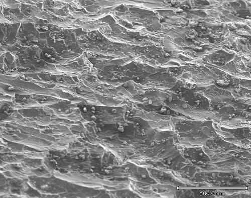
This friction reduction effect is believed to be related to sleeve surface topography. Conventional finishing processes leave pockets in the sleeve surface; if oil fills these pockets it will pressurise, taking load away from the plastic/strip contact interface and thereby reducing the friction coefficient.
To minimise oil contamination effects, sleeves are frequently cut with tread patterns. However, it is rare to find liquid oil actively flowing in the grooves, which raises questions about their effectiveness in this respect. Grooving of sleeves also appears frequently to be overdone to the point where it adversely affects sleeve compressibility — a separate and important concern discussed later.
The greatest likelihood for oil-related coil tightening problems occurs not when producing a run of oiled coils, but with the first subsequent dry coil, which is produced on a wet mandrel.
Strip End Defects and Burr
Soft IF-grade steels typically used in critical automotive skin applications are prone to a specific defect at the start of the winding process. The leading edge of the strip creates a step over which subsequent laps deform, resulting in a transverse band across the strip repeating with every mandrel rotation. This deformation slowly becomes shallower and wider as wraps increment, and spacing increases slightly with coil diameter. In galvanising lines it may be detected by careful stoning inspection up to approximately 200 metres from the start of a coil.
This effect is minimised by a soft sleeve surface. Dual durometer sleeves with a relatively thin, soft outer layer are common in automotive lines. Probably the biggest single factor in the generation of such lines is when and how sharply tension establishes at the start of coiling.
Burr on the cut end of the strip is also a consideration. Burr tends to be more pronounced with ductile grades such as IF and on thinner gauges. Its orientation (up or down relative to the sleeve) is a function of shear blade configuration and whether the coil is being under- or over-wound.
3. Stresses Within Wound Coils
Three principal stress components exist within a wound coil:
Radial stress exists between the surfaces of adjacent wraps and through the thickness of the strip itself. Radial stress is zero at the bore and at the outside diameter (O.D.) and must always be compressive at all locations between — otherwise gaps would exist between wraps. This wrap-to-wrap pressure, multiplied by the surface friction coefficient, provides the friction which gives a coil its rigidity and prevents internal slip.
Tangential stress exists in the length direction of the coiled strip. Compressive tangential stresses occur in the near-bore region of finished coils, while tensile tangential stress exists in the outer part.
Axial stress occurs in the strip width direction and is not generally important in coil winding, although significant axial loads can be incurred during stagger winding.
The simplest possible coil analogy is a shrink-fit of one tube over another. There will be a radial stress between the two contacting surfaces, with two approximately equal and opposite tangential (hoop) stresses in the tubes — tensile in the outer tube and compressive in the inner. The strength of this two-wrap assembly is related to the radial stress times area and the friction coefficient between the wraps. Full-size coils, sometimes containing thousands of wraps, follow a similar stress distribution pattern.
4. Modelling of Radial Stress
It is useful to start by considering winding a coil where the mandrel is incompressible, the strip itself is incompressible, and the strip has no transverse thickness profile. Under these idealised conditions the radial stress resulting from the application of one wrap can be calculated as:
where σr(r) is radial stress, σt(r) is tangential stress (i.e. winding tension stress), h is strip thickness and r is radius. As an example, a 1.0 mm thick strip wound on a 250 mm radius mandrel with a tension of 10.0 MPa creates a radial pressure against the mandrel surface of 0.04 MPa. Under the ideal incompressible model, further wraps increment stress on those below in a progressive and almost linear manner, with tangential stress throughout the coil remaining equal to the winding tension stress.
Early shrink-ring coil winding models developed by Sims and Place in the 1950s made similar assumptions. Calculated stress values were accurate for small numbers of wraps. However, it was subsequently shown that the calculations become increasingly inaccurate as the number of wraps increases, greatly overpredicting radial stress after just a few hundred wraps.
Strip Compressibility
A major development was made by Wadsley and Edwards (1977), who found that strip compressibility in the radial direction is approximately two orders of magnitude greater than the measured value for bulk steel. When strip surfaces are brought together, initial contact occurs only at surface peaks or asperities. The close approach distance of the surfaces is a significant proportion of strip thickness, especially for light-gauge strip with a rough surface. Under load, asperities collapse and strip surfaces move together.
Compressibility (strain per unit stress, units MPa−1) is not a single value but a curve: the material becomes progressively harder as deformation increases and real contact area grows. This characteristic is measured by compression testing a stack of sample discs in a tensile machine and determining the stress increment per unit deflection.
Such compression behaviour requires that stress modelling be done on a wrap-by-wrap basis. As each wrap is applied, the radial stress it imparts to the outside of the coil is calculated, along with how this transfers through the wraps below and how tangential stress is affected by radial compression. Internal slip potential can also be calculated based upon coil geometry, coiling tension and inter-wrap friction. After this calculation is repeated for every wrap applied, a final calculation simulates removal of bore support as the mandrel is collapsed.
5. Surface Types and Compressibility
Edwards and Bolton (2001)[1] published comparative compressibility values of 0.03 MPa−1 for tinplate and 0.075 MPa−1 for steel sheet. Galvanised strip is much more compressible, with values between 0.25 and 0.75 MPa−1 having been measured. This wide range may be due to variation in coating weight, spangle height and/or strip thickness. Note that thin strip is more compressible than thick, due to the increased number of strip-to-strip interfaces per unit of coil wall height.
The major surface types wound in galvanising lines are zinc galvanised (GI), iron-zinc galvannealed (GA) and Galvalume.
Pure zinc is relatively soft, hence surface asperities compress more easily. In the as-coated state, measured Ra roughness is low, although significant longer-range topography may exist from spangle crystals. Spangled coatings are now rare, and increasing proportions of GI are temper-rolled to create a more consistent and rougher surface. The specific roll texturing process matters: shot blasting produces a random surface, while electric discharge texturing (EDT) creates irregular steep-walled craters. These different morphologies behave quite differently under compressive load.
GA coatings are more complex. GA is quite hard (actual hardness depending on which phases are present; delta phase is harder than zeta), and as-produced GA is rough enough that temper rolling is needed to bring roughness within the normally required range.
Coil winding is in some respects a destructive process: asperity collapse is not reversible and creates a less compressible surface. Recoiling a second time with exactly the same tension will therefore produce a somewhat higher stress condition — and a tighter coil — than in the first instance. There is also potential, especially with soft GI surfaces, for coil winding to reduce measured roughness to below a customer-specified minimum.
6. Stress Calculation Examples
Making allowance for strip compressibility, stress profiles within coils can be accurately calculated. Compression reduces the buildup of radial stress in the near-bore region, while causing near-bore tangential stress to become increasingly compressive (negative).
In a typical coil winding model output, the coil winding stress is represented by the initial tension applied. A tight head end practice — involving additional tension for a short distance at the start of the coil — is common and clearly visible in the stress profiles. Light coloured lines indicate stress values at intermediate points in the winding process; the final state after mandrel collapse shows:
- Tangential stress tensile in the outer part of the coil and compressive close to the bore.
- Radial stress compressive throughout the coil.
- An initially steep rise in radial stress near the O.D., limited further into the coil by compressibility effects.
These conditions are comparable to the simple two-wrap coil analogy described earlier, confirming that the basic stress character is consistent regardless of coil size.
Treaded plastic mandrel sleeves, and even mandrels themselves, can compress, adding additional compressibility effects in the near-bore region and increasing susceptibility to almost all classes of coil winding failure. Paint lines frequently wind coils onto heavy cardboard sleeves (up to 20 mm in thickness), which are quite compressible in the thickness direction — and purchase specifications for these items rarely place limits upon this critical property.
7. Effect of Strip Shape and Profile
In practice, strip shape and transverse thickness profile will almost always create significant stress variation in the transverse direction. Winding strip with a positive transverse thickness crown produces a coil with a slightly larger diameter at its centre than at its edges — effectively a barrel. The larger centre diameter attenuates both tangential and radial stress at that location.
Strip buckle and wave defects consist of extra length, and therefore an extra mass of metal equivalent to a slight increase in strip thickness. Note however that the variation in equivalent thickness is generally not large: a 0.1% change in strip thickness produces a shape change of 100 I-units, which is large relative to a typical shape control system guarantee of 15 I-units.
Simple modelling of shape defect onset based on measured strip thickness deviation across the width is possible using a spreadsheet. In practice however, its usefulness is limited by two factors:
- The measurement accuracy of even good-quality micrometers is marginal compared to the thickness deviation necessary to create a shape defect.
- Galvanised strip surface compresses under loads generated within a wound coil, so accurately predicting shape defect onset requires compressibility measurement.
Probably the worst product in this respect is wide galvanised IF steel used for exposed automotive applications. Strip crown originates in the hot rolling process, where soft IF steel creates low rolling loads and therefore lower product crown. Occasionally the resulting strip crown may even be slightly negative.
8. Coil Winding Failure Modes
Common coil winding failure modes can all be related to the stress conditions within coils.
Slip and Telescoping
Internal slip and the telescoping which frequently accompanies it is a common coil winding problem in galvanising lines, resulting in dished coils and sometimes friction defects. Winding tension acts through a progressively increasing torque arm as the coil radius builds. The ability of underlying wraps to transfer this torque is proportional to the total interface friction of each wrap — equal to wrap area times friction coefficient times radial stress.
Wraps close to the bore are at a disadvantage due to their reduced area and the torque arm effects which increase with coil diameter. In practice, slip usually initiates at or close to the bore. The problem is exacerbated when oil reduces the friction coefficient and compressibility limits radial stress transfer into the near-bore wraps.
Corrective actions for slip include:
- Design changes to reduce sleeve and/or mandrel compressibility.
- Adoption of a winding tension profile practice — progressively reducing winding tension as coil radius increases, to maintain inner wrap torque at a safe level.
- Where the market permits, reducing coil diameter.
- Decreasing the quantity or viscosity of oil applied. Some facilities report more slipping in winter than in summer, likely due to oil viscosity changes with temperature, pointing to potential benefit from mild heating of oil and strip prior to coiling.
- Decreasing compressibility or increasing inter-wrap friction — for example by decreasing spangle size or decreasing roughness from the temper mill.
Soft Collapse
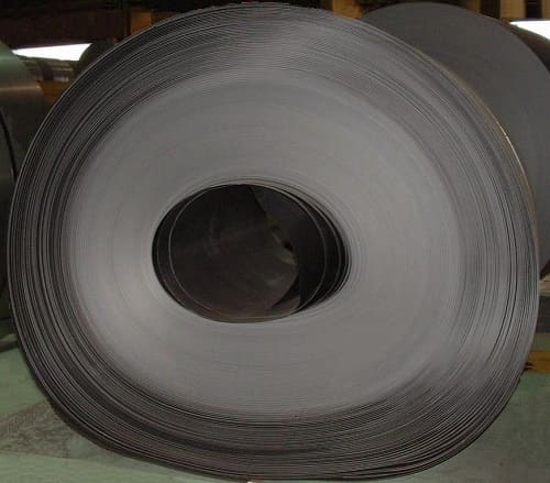
Soft collapse is associated with a lack of friction between coil wraps, allowing the coil to sag into an oval shape under loads incurred during handling. Low radial stress and a low friction coefficient are the two major contributing factors.
Inter-wrap friction is the product of friction coefficient times radial stress. The low friction condition associated with pre-lube oil application will therefore considerably increase soft collapse risk. This situation is worst when zero or negative strip transverse thickness profiles trap oil films between wraps. In severe cases a coil can soft collapse spontaneously under its own weight; more usually initiation is associated with additional handling loads, with slip propagating outward from the coil bore.
The best general solution to a plant-wide problem is to measure compressibility for different galvanised products, determine an empirical target level of radial stress, and use a winding model to establish the tension practice that will achieve the target radial stress in each case. In practice a more common corrective action is simply to increase winding tension until collapse disappears.
Hard Collapse
Hard collapse is associated with an excess of compressive tangential stress in the near-bore region. A combination of this stress condition together with a coil bore discontinuity can generate the inward kink which characterises this failure mode. The kink may then propagate through the sidewall and collapse the coil — a fully developed hard collapse can therefore sometimes be mistaken for a soft collapse.
Hard collapse is less common in galvanising lines, but when it does occur corrective actions are to reduce winding tension and to physically remove the mandrel discontinuities which serve as initiation sites. Coil failure through bore arch instability is analogous to a beam buckling calculation; attempts have been made to calculate critical mandrel defect dimensions for various levels of compressive tangential stress using this approach.
A closely related condition can occur in the case of full-hard products affected by coating buildup at their edges. Such buildup causes stress concentration, which becomes particularly high in full-hard material that does not readily relieve stress by yielding. The result is multiple small kinks visible extending throughout the sidewall but not propagating transversely into the coil.
Ridge and Buildup Defects
Both terms describe a similar problem: a localised coil diameter increase visible as a bump on the coil surface during winding. Winding tension concentrated at such locations stretches the substrate, creating a shape defect which typically manifests as pocket buckles or a tight (short) edge wave when the coil is unwound. Even a barely perceptible hump in the coil surface during winding will produce a significant shape defect.
Buildup develops progressively with each coil wrap due to a similarly localised increase in strip thickness. Incoming strip may have local thickness variations from issues such as malfunctioning rolling mill cooling sprays, or bands of different surface reactivity affecting local coating thickness. Most cases however involve the coating process itself. Strip edges constitute a discontinuity beyond which gas streams from coating control knives meet and interact, creating numerous possibilities for excess zinc thickness.
Operational solutions to the strip edge issue include slightly differential downward knife angles, but by far the preferred option is some form of edge baffle — either flat or beaver tail profile. If positioned in the same plane and close to the strip edge these can be highly effective, though maintaining smooth function in the adverse environment above the zinc bath is an ongoing practical challenge.
Edge buildup is least problematic with light (automotive) coating weights and greatest with very heavy (culvert) coatings. Galvalume and aluminised coatings use lower pressures and greater knife-to-strip distances than zinc and are therefore quite susceptible to such defects.
In the event of a ridge condition, traditional corrective actions have been to reduce coiling tension, make smaller diameter coils, or to stagger wind. Analysis shows that tension and wrap number reduction have little benefit except for marginal cases. Stagger winding can create significant axial loads and is unacceptable to many customers; its effectiveness depends on the location of the thickness ridge and the stagger parameters. Temper rolling typically has a useful effect in reducing protrusion height but is less than 100% effective and is not always available.
9. Summary
The main classes of coil winding failure — slip, soft collapse, hard collapse and ridge/buildup — can all be related to the interaction of coil winding tension and strip compressibility.
There exists a safe window for winding of stable coils, bounded by the slip, soft collapse and hard collapse failure regions. Mandrel discontinuities and mandrel collapse promote hard collapse at lower levels of winding tension. Reduced strip surface friction and increased strip compressibility require increased winding tension to avoid soft collapse. At some point, increasing compressibility will cause slipping — with the onset also related to coil diameter.
These conditions act together to narrow the window of opportunity for stable coil formation. The practical implication is that neither tension alone nor surface condition alone determines coil quality: both must be managed together, informed where possible by compressibility measurement and wrap-by-wrap stress modelling.
Key practical takeaways include:
- Strip compressibility is the most important and least measured coil winding parameter.
- Galvanised strip is significantly more compressible than uncoated steel, and compressibility varies substantially by surface type and coating weight.
- Oil dramatically reduces inter-wrap friction and should be minimised at the mandrel sleeve interface.
- Sleeve and mandrel compressibility directly worsen all classes of coil winding failure and should be minimised.
- A winding tension profile (progressively reducing tension with increasing coil radius) is generally more effective than uniform high tension in preventing slip.
- The root cause of buildup and ridge defects lies in upstream thickness and coating uniformity — operational winding adjustments are at best a partial remedy.
References
- Edwards, W.J. and Bolton, G. (2001) ‘The Mystery of Coil Winding’, Association of Iron and Steel Engineers Annual Conference.
- Li, S. and Cao, J. ‘A Study of the Stress Distribution in Coil Wrapping and its Effect on Final Coil Deformation’, Northwestern University, Evanston, Illinois.
- Hesling, S.W. (2003) ‘Coil Winding in Galvanising Lines’, Galvanisers Association Annual Meeting.
- Anderson, R., Fowkes, N. et al. (2009) ‘Analysis of Coil Slumping’.
- Norden, M. and Hesling, S.W. (2013) ‘Strip Roughness Control in Galvanising Line Temper Mills’, Galvanisers Association Annual Meeting.
Next Steps for Your Business
Coil winding problems in galvanising lines — whether slip, collapse or buildup — can result in significant reprocessing costs, product downgrades and customer complaints. A structured approach based on compressibility measurement and stress modelling can deliver:
- Reduced coil winding failures and associated reprocessing costs
- Improved coil integrity during handling and onward processing
- Better matching of winding tension practice to product type
- Reduced risk of friction and shape defects reaching the customer
If you are experiencing coil winding issues or reviewing your recoiler and tension practice, why not give us a no-obligation call? Our experts will be pleased to discuss your requirements with a view to an initial concept study.

| Temper Rolling & Tension Levelling | Strip shape principles, tension levelling and temper rolling equipment, discontinuous elongation and surface conditioning of zinc-coated strip. |
| Air Knife & Coating Mass Control | Air knife design, X-ray coating measurement, edge baffle systems and automated coating mass control in galvanising lines. |
| Dross Formation & Control | Dross composition and formation mechanisms, economic cost of coating metal loss, removal practice and aluminium bath control. |
| Plate Mill Yield and Provisioning | Provided yield and provisioning, yield cost and margin loss, plan view rolling, scale loss and hydraulic gauge control in plate mills. |
| Strip Centring in Vertical Furnaces | Roll crown mechanics, the balance between tracking-off and heat buckle, ground crown profiles, roughness and thermal crown control in vertical furnaces. |
| Side Trimming in Steel Pickle Lines | Side trimmer knife gap setup and resulting cut edge characteristics, defects from incorrect knife gap, hold-down pressure and how poor trimming causes serrated edge. |
How to Cite This Article
Hesling, S.W. (2026) ‘Coil Winding in Galvanising Lines’, SteelOnTheNet Technical Reference Series. Available at: https://www.steelonthenet.com/resources/technical/coil-winding-galvanising-lines.html (Accessed: 6th October 2026).