Gauge, Shape & Chatter Control
Published:
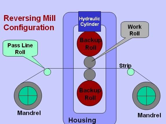
Many rolling operations take place at ambient temperature and are technically cold rolling. Light reduction temper rolling is one example, used for surface conditioning, flatness and property improvement.
This module concentrates instead on cold rolling of hot rolled and pickled coils (HRP) to make feedstock for galvanising and annealing. The scale of the operation is very large, with many millions of tonnes produced every year.
Most cold mills have a 4 Hi configuration. Small diameter driven work rolls sit between large diameter load bearing backup rolls. Hydraulic cylinders behind the backup roll chocks then give fast and precise control of roll gap.
Mills are instrumented to measure strip thickness and “shape” (flatness). That data feeds sophisticated control systems, which hold both parameters within tight tolerances.
More than one rolling pass is needed to reach the usual cold reduction of about 60%. One route is multiple backwards and forwards passes through a one or two stand reversing mill, with strip coiled on powerful mandrels each side of the mill. A single stand reversing cold mill has roughly the same 300,000 t/yr capacity as a basic commodity products galvanising line, so the two are often installed to work together.
Cold rolling may instead be performed in a single pass through a sequence of 4 or 5 stands in a tandem mill. Capacity is then very high. Coupled with a pickle line to form a continuous operation, more than 2 Mt/yr can be achieved. Product quality is high, and this is the normal route for critical automotive exposed material.
This technical module explains the fundamentals of the cold rolling process, the mill equipment and control systems involved, and the related product quality issues and corrective actions. It forms part of a series of technical reference modules authored by Steven W Hesling.
Four subjects dominate what follows. Lubrication and cooling matter because cold rolling generates significant heat in both work rolls and strip. Thickness control determines whether the product meets gauge tolerance. Shape control determines whether it lies flat, and whether downstream lines can process it. Chatter is a difficult vibration problem which can severely affect both product quality and mill output.
1. Rolling Process Basics
The rolling process has received a great deal of attention since Orowan delivered his classic analysis in 1943. That understanding was needed to develop the fast and accurate mathematical models suitable for automated systems. Here we avoid most of the mathematics and concentrate on the basic principles.
“Work Hardening”: Increase in Strength due to Deformation
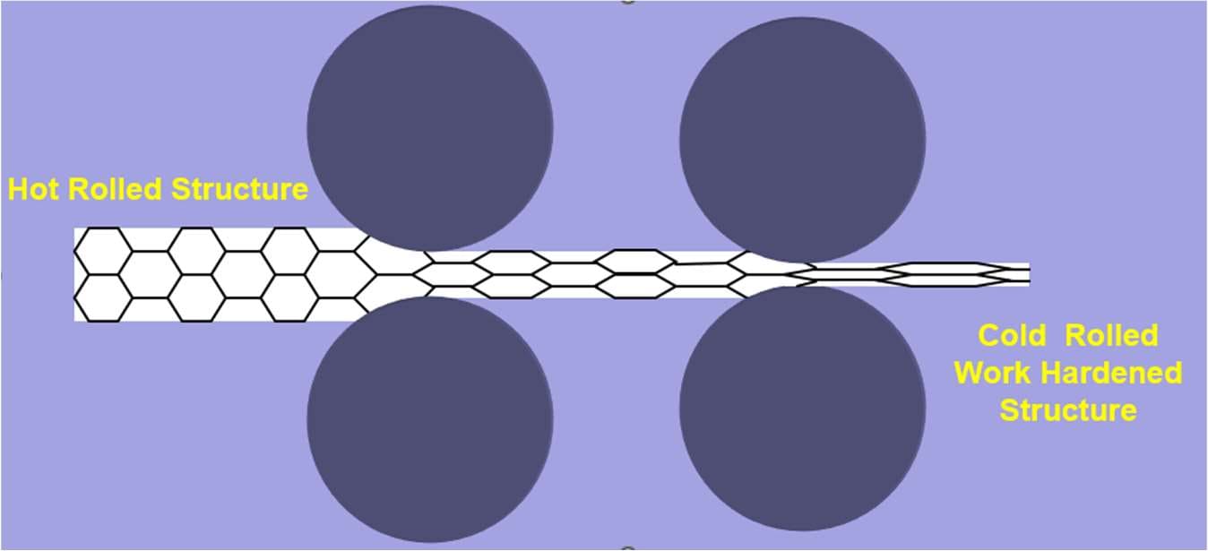
Large equiaxed grains in hot rolled strip are elongated and deformed further with each cold rolling pass. Grain boundaries eventually become difficult to discern, and the metal becomes very hard and brittle.
Typical cold mill reduction is about 60%, but it can occasionally reach 85%. Yield strength may then be increased by three times or more, and elongation (ductility) decreases until it is difficult to measure. This increase in yield strength occurs progressively during each individual rolling pass.
Mass Flow
The volume of metal entering a roll bite must equal the volume of metal leaving it. As thickness reduces, strip speed must therefore increase in inverse proportion.
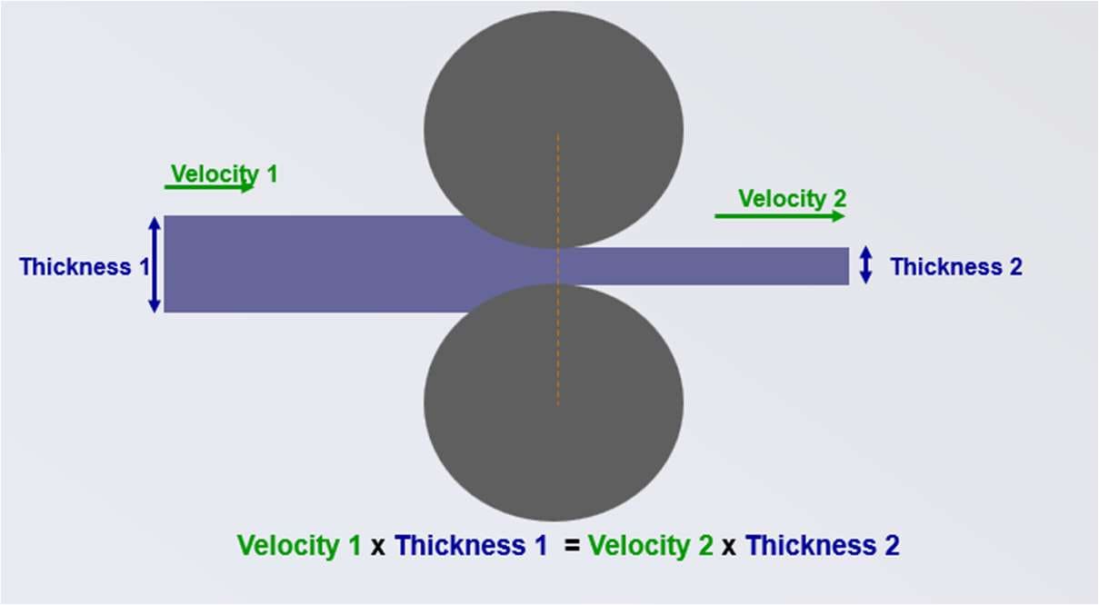
Reduce thickness by 50% in a rolling pass, and the velocity of strip leaving the mill must be double that of strip entering it. This concept is used in “mass flow” thickness control systems. Digitally regulated motor drives provide the accuracy needed to control product thickness from relative strip speeds.
The Neutral Point
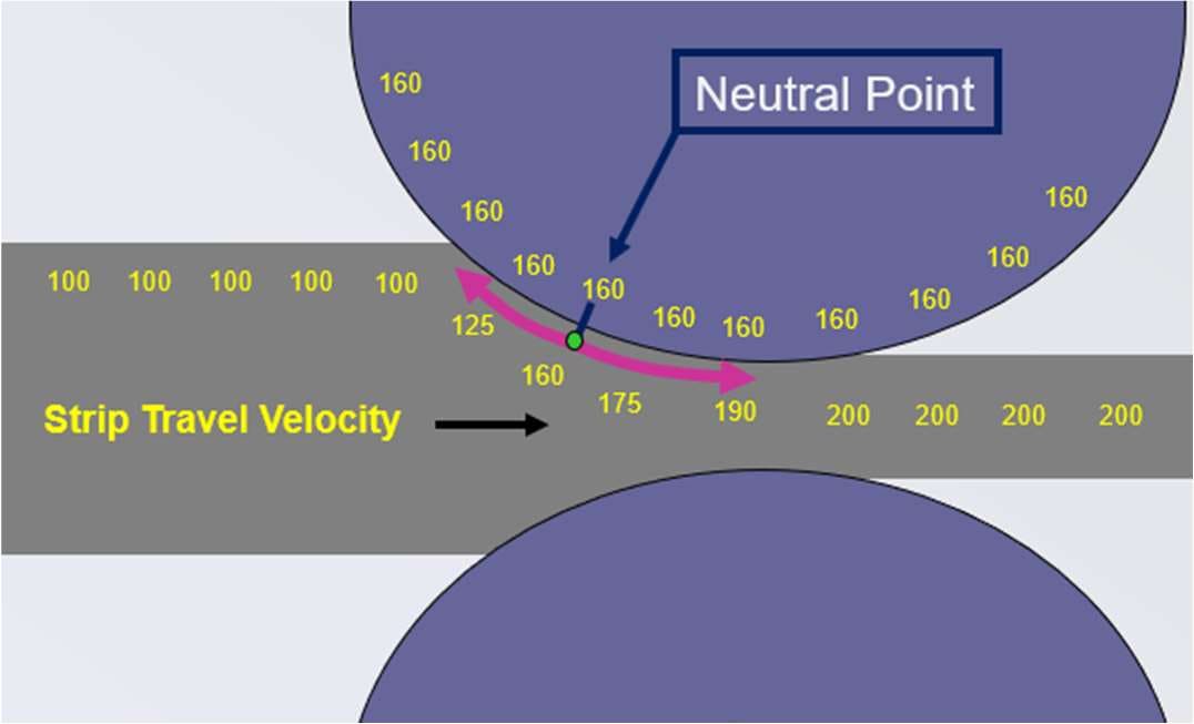
All of the roll surface is obviously travelling at the same speed. Mass flow nevertheless requires strip speed to increase as thickness reduces. A speed difference must therefore exist between roll surface and strip surface, and it changes progressively through the roll bite. At one location the two speeds are equal. This is called the neutral point.
Upstream of the neutral point, strip slips backwards across the roll face. Downstream of it, strip slips forward.
A substantial amount of heat is generated by friction between roll and strip surfaces moving at different speeds. Cold mills therefore require effective roll cooling and lubrication systems.
The “Friction Hill” Diagram
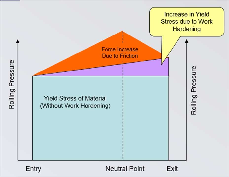
The three concepts above come together in a single diagram. It shows pressure at the roll surface, from strip entry into the roll bite through to the point where it exits. Contributions to that pressure are shown separately. Total roll separating force is equal to the area of the diagram.
- Distance from entry to exit, and therefore total rolling force, is reduced by a small work roll diameter. This is why cold mills have four rolls per stand. Large diameter backup rolls support the load, while smaller diameter work rolls decrease rolling force, electricity consumption and so on.
- Friction increases rolling force, and also electricity consumption and heat generation. Without sufficient friction, however, control of the mill decreases. We therefore manage a balancing act through selection of roll surface roughness and lubricant composition and concentration.
- Compressive yield stress of the steel is obviously the major component in this diagram. It is reduced if a tensile stress is applied to the strip. Cold mills typically operate with high entry and exit side tensions, and this is a major reason why. Tension also helps to improve strip shape and flatness.
2. Lubrication and Cooling
Cold rolling mill lubrication is an extensive subject, and is only summarised here. Note that just lubrication and cooling of roll and strip surfaces is addressed. Roll bearing lubrication is excluded.
Cold rolling mills recirculate large volumes of a water and oil “emulsion”, flooding both rolls and strip. Rolls have banks of spray nozzles extending across their entire width. These nozzles may deliver a “fan” pattern while angled slightly to provide overlap without interference. Alternative nozzle designs provide overlap with a more advanced impact pattern, shown in Fig. 6 below.

It is good practice to check impacts regularly by inserting a work roll wrapped in test paper and turning the sprays on for a few seconds. Impact locations, and any sprays showing deteriorated performance, are then easily visible.
One special and unique spray bar is installed on the last stand of the mill. It has individual on/off control for every nozzle. This bar forms part of the shape control system, where it reduces local variations by cooling the roll and thereby changing its physical profile slightly.
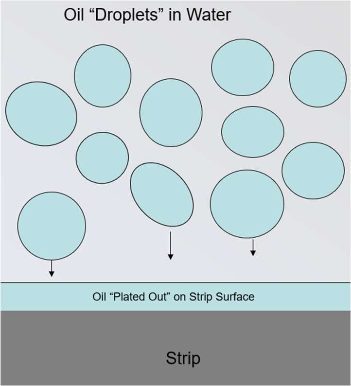
An emulsion is a semi-stable system in which small droplets of oil exist within a much larger volume of water. The water provides cooling, while oil which “plates out” on the strip and roll surfaces provides lubrication. Emulsion stability is important for achieving an appropriate degree of plate out.
Tandem cold mills typically have several oil tanks supplying combinations of rolling stands. Oil concentration in these tanks varies, typically within a range of about 3.0 to 5.0%. The last stand tank is an exception. It has a very low oil percentage, in order to achieve the oil on strip requirements of galvanising lines, which normally specify 100 to 300 milligrams of oil per square metre.
Emulsion contaminants are monitored and controlled. They include “iron fines” particles, which are removed by filtration units and magnetic separators. Another contaminant issue involves “tramp” oil from backup roll bearing lubrication leaks.
Lubrication Regimes
Lubrication can be visualised as the partial separation of two rough surfaces by an oil film. This film is plated on the strip and roll surfaces, then pulled into the roll bite by a combination of speed and its own viscosity.
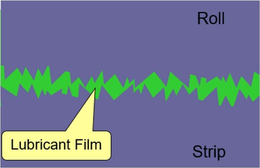
If the oil film is thinner than the roughness of the two surfaces, a stable “boundary lubrication” condition occurs. There is then some significant contacting of surface features, and friction is consistent.
Higher speeds and smoother surfaces can produce an oil film thickness which exceeds strip roughness. This undesirable case is known as hydrodynamic lubrication. The only connection between the two surfaces is then the viscosity of the oil film.
An intermediate condition, known as elasto-hydrodynamic lubrication, occurs when the oil film and the strip roughness are of similar dimension.
In tandem cold rolling, boundary lubrication normally occurs at lower speeds. Mixed boundary and elasto-hydrodynamic lubrication then occurs at higher speeds in later stands, where the strip is smoother.
3. Thickness Control
Rolling mills appear very strong, but they deform significantly under normal rolling loads. Mill housings stretch, rolls bend and flatten into oval profiles, and even the thickness of the oil film in roll bearings changes.
This stretch characteristic is defined by a number called “mill modulus”. Typical cold mills deflect about 2 mm per 1,000 tonnes of rolling force, so their mill modulus is calculated as 1000/2 = 500 tonnes/mm. Stiff modern mills may have modulus values up to about 800 t/mm.
Three measures are used in combination to overcome the problem, with a fourth addressing gauge deviation in the incoming strip.
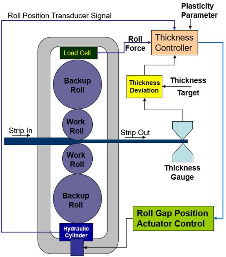
- By continuously measuring rolling force, and knowing the stiffness characteristic of the mill, a control system can infer actual strip thickness even without a direct thickness gauge measurement. It can then rapidly adjust the roll gap to compensate. Force based control has a very fast response.
- This is augmented using a downstream X-ray gauge for feedback trim (Monitor AGC).
- Hydraulic roll position actuators are also important, for fast and precise roll position correction (HAGC). Hydraulic gauge control serves the same purpose in plate mills.
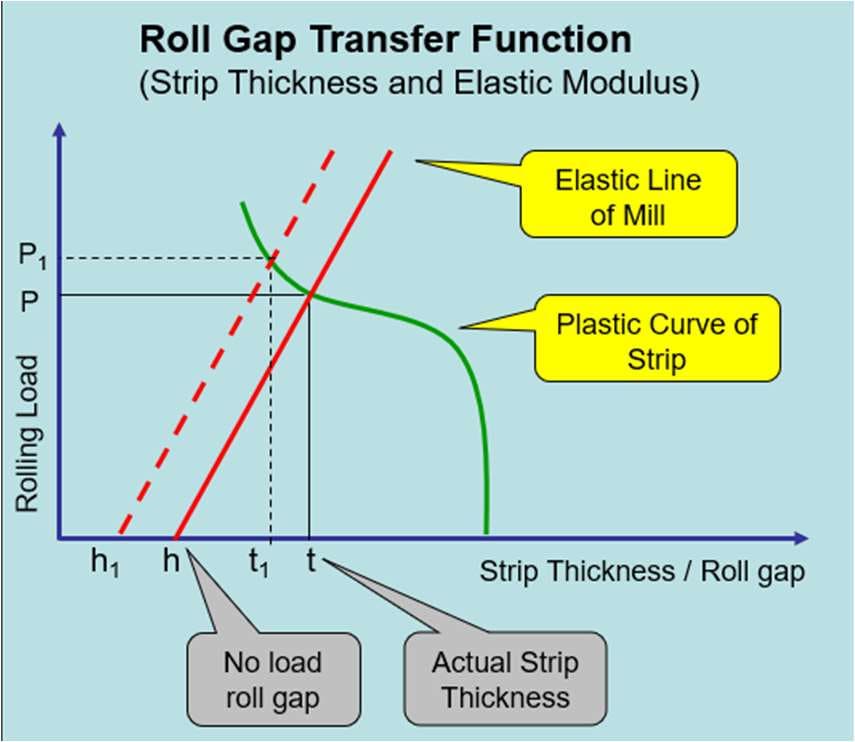
A combination of these is shown in Fig. 9a below. Note that the plasticity parameter tells the system how much of a roll position movement will go into changing mill stretch, and how much will go into changing strip thickness. The plasticity parameter is also known as the roll gap transfer function.
A diagrammatic explanation is shown in Fig. 9b. With a no-load roll gap of “h”, the actual strip thickness produced is “t” and the rolling load is “P”. Closing the no-load roll gap from “h” to “h1” will increase mill load to “P1” and decrease product thickness to t1.
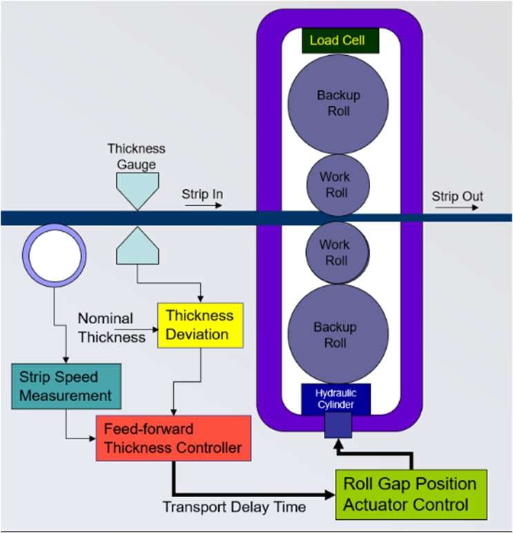
A major source of cold mill gauge variation is gauge deviation in the incoming strip. Using a thickness gauge in front of the stand, measured incoming deviations can be tracked, with a calculated correction applied just as each deviation enters the roll bite. A “feed forward” system of this type is usually used together with the system shown in Fig. 9a.
Feed forward is an open loop system requiring good parameter estimates. It is sensitive to errors in measurement of incoming thickness, which may occur because of poor strip flatness, residual lubricant and similar causes.
4. Flatness and “Shape” Control
Shape and flatness defects cause major and expensive problems with flat rolled strip products. Examples include:
- Strip breaks due to off-tracking in galvanising and annealing lines
- Coating deviations in galvanising, due to variations in air knife to strip distance
- Strip feeding problems
Mills therefore need to measure the shape of strip as it is being produced, together with a control system able to maintain this within specification. There are structural similarities between shape control systems and the thickness control systems outlined above.
Perfect flatness is not always the aim. Most external customers do want strip to be as flat as possible. Galvanising and annealing lines in the plant, however, may prefer a flatness deviation which varies by product.
Galvanising lines may want narrow and thick strip to have tight edges and a loose centre, for better tracking in their furnace. The opposite condition, two slightly wavy edges, may be preferred for wide, thin and soft strip to reduce the risk of heat buckle.
Shape, Flatness and Camber
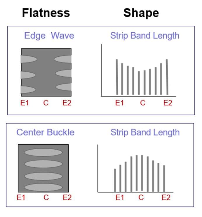
In this context, “shape” is a technical term related to length variation across the width of a strip.
Imagine cutting a piece of strip from a coil and laying it unrestrained on a flat surface. If the strip is not perfectly straight and flat, then it is exhibiting a flatness deviation.
Flatness deviations can occur at multiple locations across the width of the strip. Centre buckle and edge wave are two of the most common. All of them result from some parts of the strip being longer than others, with waves or buckles forming to accommodate the extra length.
Take that piece of strip and cut it into many narrow longitudinal bands, and they will not be identical in length. The term shape refers to this length deviation. Shape and flatness are therefore closely related, but they are not the same thing.
Camber is a condition where one edge of the strip is longer than the other. It causes strip to deviate from straight, and to attempt to curve around into a large diameter circle.
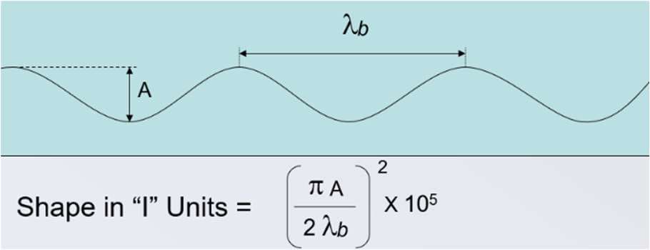
Shape is measured in “I” units, each of which is a length difference of one part in 100,000. I units are engineering strain, multiplied to give a convenient number.
It is possible to calculate shape in I units from measured wave height and length of strip on a flat surface. In this case we also need to identify where the extra length is located, giving a description such as “24 I units of edge wave”.
Measuring Shape On Line
In cold mills, on-line measurement of shape is achieved using segmented “shape rolls”. These consist of a central shaft on which many rotors are installed. Each rotor is individually capable of measuring pressure and transferring that data in real time.
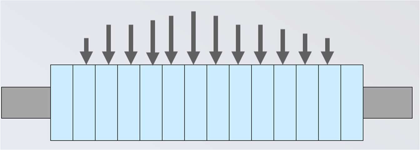
High tension applied to a strip causes buckles and waves to disappear temporarily. This is because tension stretches strip. Shorter bands are stretched more than longer bands, until everything is the same length. At this point the strip is flat, but tension varies across its width.
A shape roll measures actual tension for each segment, based on roll face pressure and wrap angle. Tension variation is then converted to length variation using Young's Modulus for steel, which is stress divided by strain.
Shape Control System Structure
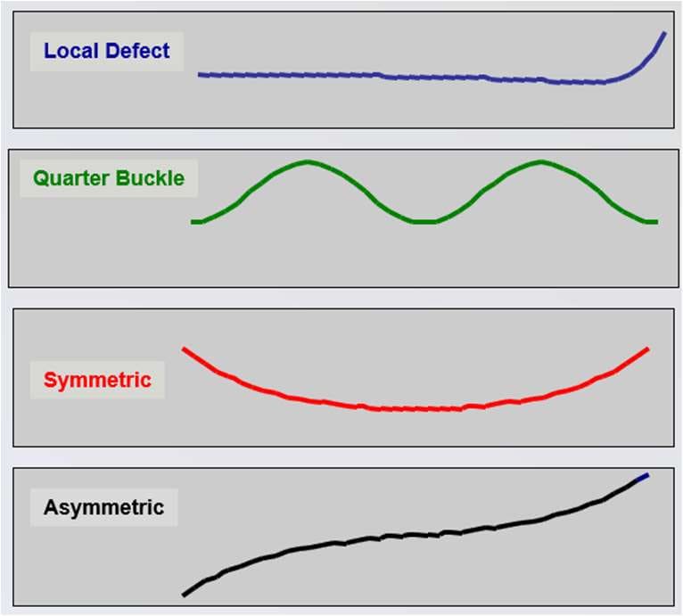
Automatic shape control systems begin by using mathematical tools to divide measured strip shape into parameter components. It is common for multiple shape errors to exist in one strip at the same time.
Different control actuators are then applied to correct each parameter, based on estimated shape change per unit of actuator input.
A symmetric component, for example, will most likely be addressed by roll bending. An asymmetric component requires a mill side-to-side level change. Local defects are corrected using the individually switched roll cooling sprays on the last stand, described in section 2 above.
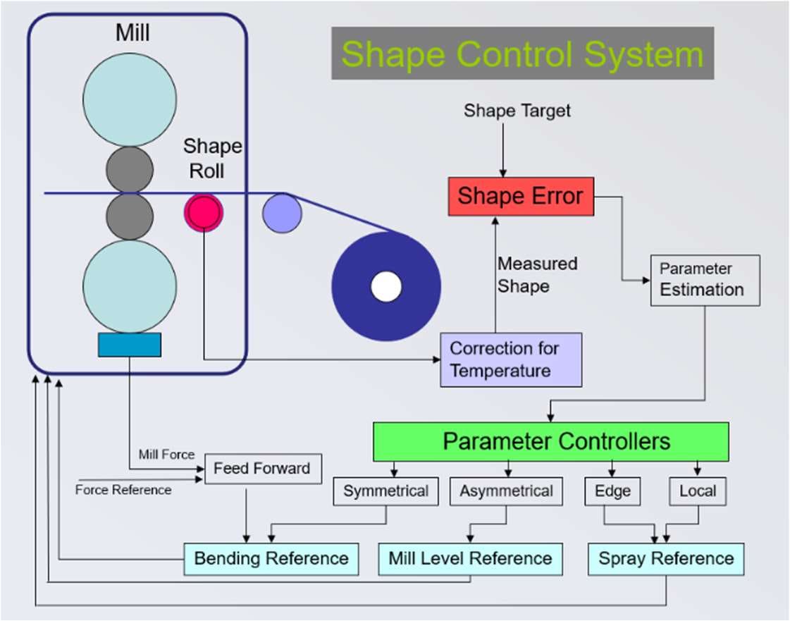
Fig. 15 shows the structure of a shape control system design. Note that it contains a fast inner loop. This responds to load changes without waiting to detect the symmetric shape change they will cause.
5. “Chatter”: Mill Vibration Related Issues
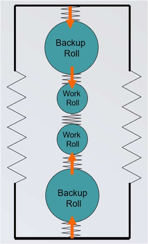
“Chatter” is a generic name for multiple mill vibration related issues. Vibration involves a spring and a mass. High frequency vibration occurs with a low mass and a strong spring, and vice versa. For vibration to continue, there must also be sustained energy input at a suitable frequency.
Multiple chatter modes exist. Each involves different movements and has a characteristic frequency range. These modes are identified as 3rd octave, 5th octave and so on. The term “octave” here is an industry classification, and differs from its use in music.
Mill stand housings, work and backup rolls, and chocks each have a mass and a spring. That creates multiple possibilities for roll stack vibration, as shown in Fig. 16.
While we normally think of vibration as a backwards and forwards movement, a shaft can also exhibit torsional (twisting) vibration.
Chatter has negative effects on the strip, and in the case of 3rd octave chatter these can be severe. It may also require a speed reduction, with consequent loss of productivity.
| Mode | Frequency | Typical Effect on Product |
|---|---|---|
| 3rd octave | About 180 Hz | Severe transverse gauge variation bands at about 150 mm intervals; risk of mill wrecks |
| 5th octave | About 600 Hz | Transverse marks on rolls and strip, with little or no thickness variation |
| Torsional | Low frequency | Transverse band markings on both rolls and strip |
3rd Octave Chatter
3rd octave chatter occurs mostly in the last and fastest stands of tandem cold mills, at about 180 Hz. It produces severe transverse gauge variation bands which repeat at about 6 inches (150 mm) intervals, and mill wrecks can also occur. Roll movements are probably similar to those in Fig. 16 above. This mode appears to be energised by stand-to-stand tension and thickness interactions.
A range of actions may reduce 3rd octave chatter. For example:
- Accelerometers mounted on mill housings and roll chocks may be used to detect onset and automatically reduce mill speed before chatter becomes severe.
- Tighter control of work roll roughness and rolling lubricant condition stabilises friction within a narrower range, because friction contributes to damping the system.
- “Tuned” weights added to roll chocks may be used to move the onset frequency.
5th Octave Chatter

5th octave chatter occurs at about 600 Hz. It produces transverse marks on both rolls and strip, but little if any strip thickness variation. Its exact mechanism remains in some doubt. It appears to be a single stand roll bite phenomenon, possibly associated with the lubrication regime cycling rapidly between boundary, mixed and hydrodynamic modes.
A number of methods have been proposed to avoid 5th octave chatter, or at least to raise its onset. These include selecting work roll and backup roll diameters which avoid certain critical ratios, and regularly changing rolling speeds to move mark locations on the rolls before they develop significantly.
Torsional Vibration
Torsional vibration occurs in cold rolling mills and is a twisting oscillation caused by torsional loading and unloading of the drive train. The drive train consists of the motor, gearbox, spindle and roll.
It is entirely different from 3rd and 5th octave chatter, which involve bending and structural distortion of the stand, chocks and similar components. Torsional vibration occurs at low frequencies and produces transverse band markings on both rolls and strip.
6. Roll Marks
This defect is caused by damage, metal flakes or other material on a work roll surface, creating a mark on the strip every time the roll rotates. The strip marking can be an “impression” or an “expression”, depending on whether the roll has a bump or a hole in its surface.
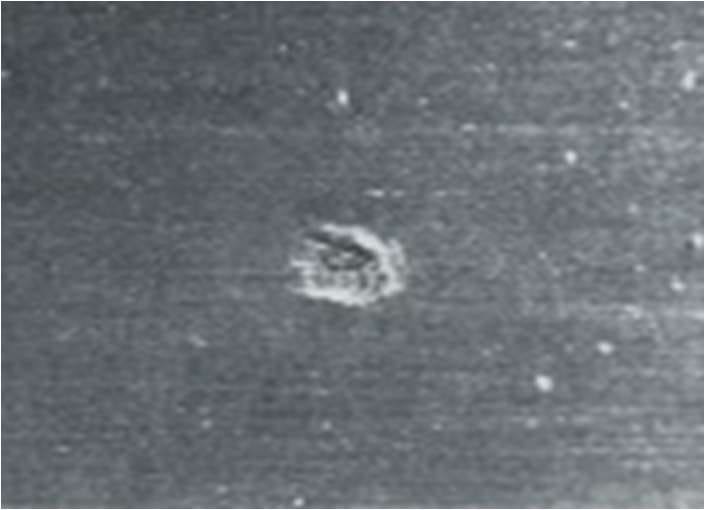
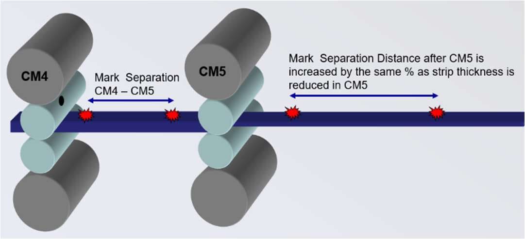
Tandem cold mills make routine “run out” inspections of coils to locate these defects. They must then identify rapidly and accurately which rolling stand created a mark, so that its work rolls can be changed before any more product is made. To do this, we measure mark separation spacing. We then use the known work roll diameters in each mill stand, together with the percentage reduction in each stand, to calculate back to the source roll.
Next Steps for Your Business
Well set up cold mill process and control systems deliver measurable benefits across the downstream route, including:
- Tighter gauge tolerance and improved prime yield from the cold mill
- Shape delivered to the specification each galvanising or annealing line actually wants
- Lower risk of chatter related gauge bands, speed restrictions and mill wrecks
- Faster identification of the stand responsible for roll marks, and less product at risk
If you are looking to optimise operating performance of your cold rolling mill, and to assess functionality of its control systems, why not give us a no-obligation call? Our experts will be pleased to discuss your requirements with a view to an initial concept study.
152 projects in 48 countries since 2001
Free, confidential first conversation No obligation Reply within one working day

| Temper Rolling & Tension Levelling | Strip shape principles, tension levelling and temper rolling equipment, discontinuous elongation and surface conditioning of zinc-coated strip. |
| Side Trimming in Steel Pickle Lines | Side trimmer knife gap setup and resulting cut edge characteristics, defects from incorrect knife gap, hold-down pressure and how poor trimming causes serrated edge. |
| Strip Centring in Vertical Furnaces | Roll crown mechanics, the balance between tracking-off and heat buckle, ground crown profiles, roughness and thermal crown control in vertical furnaces. |
| Air Knife & Coating Mass Control | X-ray coating mass measurement, ASTM specifications, air knife design and setup, edge baffles and automated coating weight control. |
| Coil Winding in Galvanising Lines | Radial and tangential stress in wound coils, strip compressibility, telescoping and other winding failure modes and corrective actions. |
| Dross Control in Zinc Galvanising Lines | Dross formation, composition and cost in zinc galvanising lines, including top and bottom dross mechanisms and removal practice. |
| Plate Mill Yield and Provisioning | Plate yield and provisioning, yield cost and margin loss, plan view rolling, scale loss and hydraulic gauge control in plate mills. |
How to Cite This Article
Hesling, S.W. (2026) 'Cold Rolling of Steel Strip for Galvanised and Annealed Products', SteelOnTheNet Technical Reference Series. Available at: https://www.steelonthenet.com/resources/technical/cold-rolling-mill-gauge-shape-control.html (Accessed: 26 October 2026).